EXHIBIT 10.16
Confidential Materials omitted and filed separately with the
Securities and Exchange Commission. Asterisks denote omissions.
REVISED FINAL PROPOSAL
DOE Savannah River Site
Biomass Cogeneration Facility and
K and L Area Heating Plants
Submitted by:
Ameresco Federal Solutions
1820 Midpark Road, Suite C
Knoxville, TN 37921
Under DOE Contract No. DE-AM36-02NT41457
May 11, 2009
DISCLOSURE OF INFORMATION
This proposal includes data that shall not be disclosed outside the Government and shall not
be duplicated, used, or disclosed—in whole or in part—for any purpose other than to evaluate this
proposal. If, however, a contract is awarded to this offeror as a result of—or in connection
with—the submission of this data, the Government shall have the right to duplicate, use, or
disclose the data to the extent provided in the resulting contract. This restriction does not
limit the Government’s right to use information contained in this data if it is obtained from
another source without restriction. The data subject to this restriction are contained on all
pages.
|
|
|
Revised Final Proposal – May 11, 2009
Ameresco Federal Solutions
Page i
|
|
Biomass Cogeneration Facility and Heating Plants
Savannah River Site
Contract DE-AM36-02NT41457 |
TABLE OF CONTENTS
| |
|
|
|
|
EXECUTIVE SUMMARY |
|
|
1 |
|
1.0 ECM 1 DESCRIPTION |
|
|
4 |
|
1.1 ECM Summary Schedule DO-4 |
|
|
4 |
|
1.2 ECM #1: Biomass Cogeneration Facility |
|
|
4 |
|
1.2.1 Detailed Description of ECM |
|
|
4 |
|
1.2.1.1 ECM Summary |
|
|
4 |
|
1.2.1.2 ECM Design Process |
|
|
5 |
|
1.2.1.3 ECM 1 Operation |
|
|
17 |
|
1.2.2 Location Affected |
|
|
18 |
|
1.2.3 ECM 1 Interface with Government Equipment |
|
|
20 |
|
1.2.4 Proposed Equipment |
|
|
25 |
|
1.2.5 Expected Lifetime |
|
|
25 |
|
1.2.6 Physical Changes to Existing Equipment or Facilities |
|
|
25 |
|
1.2.7 Savings Proposed |
|
|
25 |
|
1.2.7.1 Annual Project Savings Overview |
|
|
25 |
|
1.2.7.2 Annual Energy Baseline Consumption & Costs |
|
|
27 |
|
1.2.7.3 Annual Energy Savings Calculations |
|
|
30 |
|
1.2.7.4 ECM 1 Performance Measurement |
|
|
30 |
|
1.2.8 Utility Interruptions |
|
|
35 |
|
1.2.9 Agency Support Required |
|
|
35 |
|
1.2.10 Potential Environmental Impact |
|
|
35 |
|
1.2.11 ECM Property Ownership |
|
|
35 |
|
1.2.12 ECM Project Schedule |
|
|
35 |
|
1.3 BAMF Project Components |
|
|
36 |
|
1.3.1 BAMF Resource |
|
|
36 |
|
1.3.1.1 BAMF Supply |
|
|
36 |
|
1.3.1.2 BAMF Pricing |
|
|
37 |
|
1.3.1.3 BAMF Acquisition |
|
|
38 |
|
1.3.2 BAMF Transportation, Metering, & Delivery |
|
|
38 |
|
1.3.2.1 BAMF Transportation & Delivery |
|
|
38 |
|
1.3.2.2 BAMF Metering |
|
|
38 |
|
1.3.3 BAMF
End-Use Project |
|
|
39 |
|
1.3.3.1 BAMF End-Use Demand |
|
|
39 |
|
1.3.3.2 BAMF End-Use Operations & Maintenance |
|
|
39 |
|
2.0 ECM 2 DESCRIPTION |
|
|
40 |
|
Use or disclosure of data contained on this sheet is subject to the restriction on the first page of this proposal
|
|
|
Revised Final Proposal – May 11, 2009
Ameresco Federal Solutions
Page ii
|
|
Biomass Cogeneration Facility and Heating Plants
Savannah River Site
Contract DE-AM36-02NT41457 |
| |
|
|
|
|
|
2.1 ECM Summary Schedule DO-4 |
|
|
40 |
|
2.2 ECM #2: Biomass Heating Plants for K& L Areas |
|
|
40 |
|
2.2.1 Detailed Description of ECM |
|
|
40 |
|
2.2.1.1 ECM Summary |
|
|
40 |
|
2.2.1.2 ECM Process Description |
|
|
41 |
|
2.2.1.3 ECM Operation |
|
|
42 |
|
2.2.2 Location Affected |
|
|
43 |
|
2.2.3 ECM 2 Interface with Government Equipment |
|
|
44 |
|
2.2.4 Proposed Equipment |
|
|
46 |
|
2.2.5 Expected Lifetime |
|
|
46 |
|
2.2.6 Physical Changes to Existing Equipment or Facilities |
|
|
46 |
|
2.2.7 Savings Proposed |
|
|
46 |
|
2.2.7.1 Annual Energy Savings |
|
|
49 |
|
2.2.7.2 Annual Energy Baseline Consumption & Costs |
|
|
49 |
|
2.2.7.3 Annual Heating Plant Performance |
|
|
51 |
|
2.2.8 Utility Interruptions |
|
|
52 |
|
2.2.9 Agency Support Required |
|
|
52 |
|
2.2.10 Potential Environmental Impact |
|
|
52 |
|
2.2.11 ECM Property Ownership |
|
|
52 |
|
2.2.12 ECM Project Schedule |
|
|
53 |
|
3.0 ENVIRONMENTAL IMPACT OVERVIEW |
|
|
54 |
|
3.1 Overview of Environmental Benefits |
|
|
54 |
|
3.2 Overview of Environmental Permitting & Assessment |
|
|
54 |
|
4.0 ECM PERFORMANCE MEASUREMENT |
|
|
59 |
|
4.1 Overview of Proposed Annual Savings |
|
|
59 |
|
4.2 M&V Plan Executive Summary |
|
|
59 |
|
4.3 Whole Project Data / Global Assumptions |
|
|
60 |
|
4.3.1 Risk and Responsibility |
|
|
60 |
|
4.3.2 Energy, Water, and Operations and Maintenance (O&M) Rate Data |
|
|
60 |
|
4.3.3 Schedule & Reporting for Verification Activities |
|
|
61 |
|
4.3.4 Status of Utility Company Incentives |
|
|
62 |
|
4.4 ECM Specific M&V Plan and Savings Calculation Methods |
|
|
62 |
|
4.4.1 Overview of ECM Specific M&V Plans |
|
|
62 |
|
4.4.1.1 ECM 1: Biomass Cogeneration Facility |
|
|
62 |
|
4.4.1.2 ECM 2: Biomass Heating Plants for K& L Areas |
|
|
62 |
|
Use or disclosure of data contained on this sheet is subject to the restriction on the first page of this proposal
|
|
|
Revised Final Proposal – May 11, 2009
Ameresco Federal Solutions
Page iii
|
|
Biomass Cogeneration Facility and Heating Plants
Savannah River Site
Contract DE-AM36-02NT41457 |
| |
|
|
|
|
|
4.4.2 Energy and Water Baseline Development |
|
|
62 |
|
4.4.3 Proposed Energy & Water Savings Calculations and Methodology |
|
|
62 |
|
4.4.4 Operations and Maintenance Cost Savings |
|
|
62 |
|
5.0 MANAGEMENT APPROACH |
|
|
63 |
|
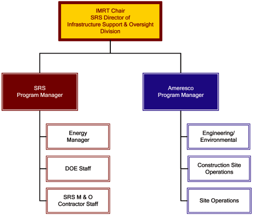
5.1 Integrated Management Review Team (IMRT) |
|
|
63 |
|
5.2 Ameresco Management Approach |
|
|
64 |
|
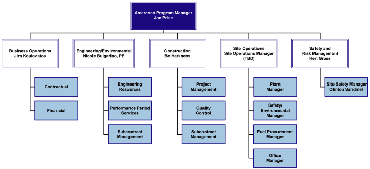
5.2.1 Ameresco Corporate Management Team |
|
|
66 |
|
5.2.2 Program Manager |
|
|
68 |
|
5.2.3 Engineering |
|
|
68 |
|
5.2.4 Business Operations |
|
|
68 |
|
5.2.5 Safety and Risk Management |
|
|
68 |
|
5.2.5.1 Site Safety Management |
|
|
68 |
|
5.2.6 Construction |
|
|
69 |
|
5.2.6.1 Subcontract Management |
|
|
69 |
|
5.2.6.2 Construction Management |
|
|
69 |
|
5.2.7 Site Operations |
|
|
70 |
|
5.2.7.1 Operations and Maintenance Responsibilities |
|
|
70 |
|
5.2.7.2 Repair & Replacement Responsibilities |
|
|
74 |
|
5.3 ECM Training |
|
|
74 |
|
5.4 Risk/Responsibility Matrix |
|
|
75 |
|
6.0 PROPOSAL PRICING INFORMATION |
|
|
88 |
|
6.1 Interest Rate |
|
|
88 |
|
6.2 Finance Procurement Price |
|
|
88 |
|
6.3 Sales Tax |
|
|
89 |
|
6.4 Property Tax |
|
|
90 |
|
6.5 Insurance |
|
|
90 |
|
6.6 Payment/Term |
|
|
90 |
|
6.7 Cancellation/Termination/Buyout |
|
|
91 |
|
6.8 Prepayments/Buydowns |
|
|
92 |
|
6.9 Protection of Financier’s Interest |
|
|
92 |
|
6.10 Security Interest in ECM Equipment |
|
|
93 |
|
6.11 Assignment of Claims |
|
|
93 |
|
6.12 Title to and Responsibility for Contractor Installed-Property |
|
|
93 |
|
6.13 Construction Milestones |
|
|
94 |
|
Use or disclosure of data contained on this sheet is subject to the restriction on the first page of this proposal
|
|
|
Revised Final Proposal – May 11, 2009
Ameresco Federal Solutions
Page iv
|
|
Biomass Cogeneration Facility and Heating Plants
Savannah River Site
Contract DE-AM36-02NT41457 |
APPENDICES
Appendices A through E and G are presented in Volume II.
Appendix F is presented in Volume III.
| |
|
|
|
|
|
APPENDIX A – GEOTECHNICAL REPORT |
|
|
A-1 |
|
APPENDIX B – FLOW DIAGRAMS FOR BIOMASS COGENERATION PLANT |
|
|
B-1 |
|
APPENDIX C – EQUIPMENT LIST & MANUFACTURER INFORMATION SHEETS |
|
|
C-1 |
|
APPENDIX D– DESIGN STANDARDS MATRIX |
|
|
D-1 |
|
APPENDIX E – PROJECT SCHEDULE |
|
|
E-1 |
|
APPENDIX F – PRELIMINARY DESIGN DRAWINGS |
|
|
F-1 |
|
APPENDIX G – REVIEW COMMENTS |
|
|
G-1 |
|
Use or disclosure of data contained on this sheet is subject to the restriction on the first page of this proposal
|
|
|
Revised Final Proposal – May 11, 2009
Ameresco Federal Solutions
Page v
|
|
Biomass Cogeneration Facility and Heating Plants
Savannah River Site
Contract DE-AM36-02NT41457 |
List of Figures
| |
|
|
|
|
|
Figure 1.1: Proposed Cogeneration Facility Site Layout |
|
|
7 |
|
Figure 1.2: EPI Fluidized Bed Energy System |
|
|
10 |
|
Figure 1.3: EPI Fluidized Bed Cell |
|
|
11 |
|
Figure 1.4: Cogeneration Facility Site Location |
|
|
19 |
|
Figure 1.5: Biomass Cogeneration Facility Steam Interconnection |
|
|
21 |
|
Figure 1.6: Biomass Cogeneration Facility River Water Interconnection |
|
|
22 |
|
Figure 2.1: K Area Biomass Heating Plant Location |
|
|
44 |
|
Figure 2.2: L Area Biomass Heating Plant Location |
|
|
44 |
|
Figure 5.1: Integrated Management Review Team |
|
|
64 |
|
Figure 5.2: Ameresco’s SRS Biomass Project Team |
|
|
67 |
|
Figure 5.3: Proposed Operations Staffing |
|
|
73 |
|
List of Tables
| |
|
|
|
|
|
Table ES.1: Project Economic Summary |
|
|
2 |
|
Table 1.1: SRS Site Projection Profile – Steam Demand |
|
|
17 |
|
Table 1.2: Utility Interconnection Summary |
|
|
20 |
|
Table 1.3: ECM 1 Annual Savings Summary |
|
|
26 |
|
Table 1.4: O&M Baseline Costs for D-Area Plant |
|
|
28 |
|
Table 1.5: Baseline Energy Consumption |
|
|
29 |
|
Table 1.6: ECM 1 Post-ECM Implementation Facility Performance |
|
|
33 |
|
Table 1.7: Project Milestones |
|
|
35 |
|
Table 2.1: Utility Interconnection Summary |
|
|
44 |
|
Table 2.2: ECM 2 Annual Savings Summary |
|
|
48 |
|
Table 2.3: Baseline Operating and Maintenance Cost for K Area Plant |
|
|
50 |
|
Table 2.4: Baseline Annual Energy Consumption for K Area Plant |
|
|
51 |
|
Table 2.5: ECM 2 Post ECM Heating Plant Performance |
|
|
52 |
|
Table 2.6: ECM 2 Annual Post ECM Non-Fuel Utilities Cost & Consumption |
|
|
52 |
|
Table 3.1: Environmental Permits & Documents |
|
|
55 |
|
Table 3.2: Annual Emissions Summary for Biomass Cogeneration Facility |
|
|
57 |
|
Table 3.3: Annual Emissions Summary for K&L Heating Plants |
|
|
57 |
|
Table 4.1: M&V Plan Summary |
|
|
59 |
|
Table 4.2: Utility Cost for ECM (Post) |
|
|
60 |
|
Table 4.3: NIST Escalation Rates |
|
|
61 |
|
Use or disclosure of data contained on this sheet is subject to the restriction on the first page of this proposal
|
|
|
Revised Final Proposal – May 11, 2009
Ameresco Federal Solutions
Page vi
|
|
Biomass Cogeneration Facility and Heating Plants
Savannah River Site
Contract DE-AM36-02NT41457 |
LIST OF ABBREVIATIONS & ACRONYMS
| |
|
|
|
ACSR
|
|
Aluminum Conductor, Steel Reinforced |
AIA
|
|
American Institute of Architects |
ASG
|
|
Annual Steam Guarantee |
BAMF
|
|
Biomass & Alternate Methane Fuel |
BDF
|
|
Bio Derived Fuel |
BFB
|
|
Bubbling Fluidized Bed |
Btu
|
|
British Thermal Unit |
CATEX
|
|
Categorical Exclusion |
CO
|
|
Carbon Monoxide |
CO2
|
|
Carbon dioxide |
CY
|
|
Calendar Year |
DA
|
|
Deaerator |
DC
|
|
Direct Current |
DDC
|
|
Direct Digital Control |
DES
|
|
Detailed Energy Survey |
DOE
|
|
Department of Energy |
EA
|
|
Environmental Assessment |
ECM
|
|
Energy Conservation Measure |
EPA
|
|
Environmental Protection Agency |
EPI
|
|
Energy Products of Idaho |
ESPC
|
|
Energy Savings Performance Contract |
°F
|
|
Degrees Fahrenheit |
FAR
|
|
Federal Acquisition Regulation |
FEMP
|
|
Federal Energy Management Program |
FONSI
|
|
Finding of No Significant Impact |
FY
|
|
Fiscal Year |
gpm
|
|
Gallons per Minute |
Hp
|
|
Horsepower |
ID
|
|
Induced Draft |
IMRT
|
|
Integrated Management Review Team |
IPMVP
|
|
International Performance Measurement & Verification Protocol |
kgal
|
|
Kilogallons |
klbs
|
|
Kilopounds |
kV
|
|
Kilovolts |
KVA
|
|
Kilovolt Amperes |
Use or disclosure of data contained on this sheet is subject to the restriction on the first page of this proposal
|
|
|
Revised Final Proposal – May 11, 2009
Ameresco Federal Solutions
Page vii
|
|
Biomass Cogeneration Facility and Heating Plants
Savannah River Site
Contract DE-AM36-02NT41457 |
| |
|
|
|
kW
|
|
Kilowatt |
kWh
|
|
Kilowatt hour |
LEED
|
|
Leadership in Energy and Environmental Design |
M & O
|
|
Management and Operations |
M & V
|
|
Measurement and Verification |
MBtu
|
|
Million British Thermal Units (1 x 10⁶) |
MOA
|
|
Memorandum of Agreement |
MOU
|
|
Memorandum of Understanding |
MVAR
|
|
Megavolt Ampere Reactive |
MW
|
|
Megawatts |
NEPA
|
|
National Environmental Policy Act |
NFPA
|
|
National Fire Protection Association |
NIST
|
|
National Institute of Standards & Technology |
NOI
|
|
Notice of Intent to Award |
NOx
|
|
Nitrogen Oxide |
NPDES
|
|
National Pollutant Discharge Elimination System |
O & M
|
|
Operations and Maintenance |
PA
|
|
Public Address |
PM
|
|
Particulate Matter |
PMT
|
|
Project Management Team |
POIC
|
|
Point of Interconnection |
PPEF
|
|
Performance Period Escrow Fund |
PPH
|
|
Pounds Per Hour |
PRV
|
|
Pressure Reducing Valve |
Psig
|
|
Pounds per square inch gauge |
PSUP
|
|
Power Services Utilization Permit |
PT
|
|
Potential Transformer |
PVC
|
|
Polyvinyl Chloride |
QC
|
|
Quality Control |
QCM
|
|
Quality Control Manager |
REC
|
|
Renewable Energy Credit |
RO
|
|
Reverse Osmosis |
ROW
|
|
Right of Way |
SCADA
|
|
Supervisory Control and Data Acquisition |
SCDHEC
|
|
South Carolina Department of Health & Environmental Control |
SCDOT
|
|
South Carolina Department of Transportation |
SCE&G
|
|
South Carolina Electric & Gas |
Use or disclosure of data contained on this sheet is subject to the restriction on the first page of this proposal
|
|
|
Revised Final Proposal – May 11, 2009
Ameresco Federal Solutions
Page viii
|
|
Biomass Cogeneration Facility and Heating Plants
Savannah River Site
Contract DE-AM36-02NT41457 |
| |
|
|
|
SNCR
|
|
Selective Non Catalytic Reduction |
SO2
|
|
Sulfur Dioxide |
SRS
|
|
Savannah River Site |
SRNS
|
|
Savannah River Nuclear Solutions |
SSM
|
|
Site Safety Manager |
VAC
|
|
Volts Alternating Current |
VFD
|
|
Variable Frequency Drive |
VOC
|
|
Volatile Organic Compound |
Yr
|
|
Year |
Use or disclosure of data contained on this sheet is subject to the restriction on the first page of this proposal
|
|
|
Revised Final Proposal — May 11, 2009
Ameresco Federal Solutions
Page 1
|
|
Biomass Cogeneration Facility and Heating Plants
Savannah River Site
Contract DE-AM36-02NT41457 |
EXECUTIVE SUMMARY
This Revised Final Proposal (Final Proposal) submitted by Ameresco Federal Solutions, Inc.
(Ameresco) is for the implementation of two biomass Energy Conservation Measures (ECMs) at the
Department of Energy’s (DOE) Savannah River Site (SRS), located in South Carolina, approximately 18
miles south of Aiken and 20 miles east of Augusta, Georgia. The ECMs are being proposed under the
authority and terms of the DOE Biomass and Alternate Methane Fuel (BAMF) Energy Savings Performance
Contract number DE-AM36-02-NT41457 as modified by DO RFP # DE-RP09-09SR22572, dated February 26,
2009. This Revised Final Proposal including technical, pricing, and management data shall remain
valid through June 15, 2009.
The proposal consists of two Energy Conservation Measures (ECMs). ECM 1 provides for the turnkey
installation of a new Biomass Cogeneration Facility with a design capacity of 240,000 pounds per
hour (PPH) of steam and 20 megawatts (MW) of electric power. The new facility will replace the
existing D Area coal-fired cogeneration plant. ECM 2 includes the turnkey installation of two 10,500 PPH
steam heating facilities; one to be located in the K Area and one to be located in the L Area.
These systems will replace the aging fuel oil-fired packaged boilers currently serving the K and L
Areas of the site.
The existing D Area cogeneration plant produces both steam and electricity that is consumed on
site. The steam is delivered through a large distribution pipeline that runs several miles from
the plant to the end-user facilities. The plant also produces approximately 15 MW of electricity
that is consumed by DOE facilities on site. The 1950s era plant is fueled by coal and in need of
significant modifications to bring the plant into compliance with current environmental
requirements as well as to be a reliable source of energy. The proposed Biomass Cogeneration
Facility, sited near the existing steam interconnection at the intersection of Burma Road and C
Road, will significantly reduce the distance from the plant to the end-user, resulting in improved
operating efficiency. The new facility will have enough capacity to satisfy all of the site’s
steam requirements and a significant portion of the electrical demand which will allow for the D
Area plant to be shut down.
Currently, the existing heating plant in the K Area provides steam for both the K and L Areas.
Steam is delivered from the K Area plant to L Area facilities through a 6”, 2.5 mile pipeline. ECM
2 provides for replacing the K Area plant with two 10,500 PPH boilers — one boiler located in K
Area and one located in L Area — eliminating the need to use the 2.5 mile distribution line. The
existing K Area plant and the steam line will be shut down.
Clean biomass and bio-derived fuels (BDF) will be the primary fuel source for all of the new
boilers. The clean biomass consists of various types of forest residues, and the BDF consists
primarily of scrapped vehicle tires. Fuel deliveries will be received by Ameresco staff at a fuel handling yard located
within the Biomass Cogeneration Facility site at the Burma Road/C Road location. The fuel handling
yard includes a fuel receiving, storage, and processing area that will serve the Biomass
Cogeneration Facility and the K and L Area Heating Plants. Fuel deliveries to the K and L Area
Heating Plants will be made by Ameresco staff on an as-needed basis from the central fuel yard.
Use or disclosure of data contained on this sheet is subject to the restriction on the first page of this proposal
|
|
|
Revised Final Proposal — May 11, 2009
Ameresco Federal Solutions
Page 2
|
|
Biomass Cogeneration Facility and Heating Plants
Savannah River Site
Contract DE-AM36-02NT41457 |
The use of renewable energy fuel sources provides many positive economic and environmental
benefits to the SRS and the local community, while providing significant energy and cost savings to
SRS. The savings result from fuel switching (coal to biomass), reductions in line losses by
locating the new cogeneration facility and heating plants closer to end-user facilities, and
improved efficiencies from new equipment sized to better match existing load requirements. Key
environmental benefits of the project include:
| |
• |
|
Over 2,000,000 MBtu/yr of thermal renewable energy production and a minimum
generation of 77,000 mWh (264,444 MBtu) of green power. |
| |
| |
• |
|
Annual Energy Savings of approximately 500,000 MBtu/yr |
| |
| |
• |
|
No-cost Renewable Energy Credits (RECs) |
| |
| |
• |
|
Decrease of water intake from the Savannah River by 1,412,000
kgal/yr, supporting water conservation efforts in the regional drought situation. |
| |
| |
• |
|
Reduction of 400 tons/yr of Particulate Matter (PM) emissions |
| |
| |
• |
|
Reduction of 3,500 tons/yr of Sulfur Dioxide (SO2) emissions |
| |
| |
• |
|
Reduction of 100,000 tons/yr of Carbon Dioxide (CO2) emissions |
| |
| |
• |
|
Support of the South Carolina Biomass Council Goals |
Ameresco proposes to provide a turnkey package of design, permitting, and installation. Ameresco
will also take responsibility for the operation and maintenance of the cogeneration facility and
heating plants throughout the contract term. Table ES.1 below provides an overview of project
economics (as shown on Schedule DO-4) for Performance Period Year 1.
Table ES.1: Project Economic Summary
| |
|
|
|
|
|
|
|
|
|
|
|
|
|
|
|
|
|
|
|
|
| |
|
Project |
|
|
|
|
|
|
|
|
|
|
|
|
|
| |
|
Implementation |
|
|
Total Energy Savings |
|
|
O&M Savings |
|
|
Water Savings |
|
|
Total Savings |
|
| Project |
|
Cost* |
|
|
(Year 1, 2012) |
|
|
(Year 1, 2012) |
|
|
(Year 1, 2012) |
|
|
(Year 1, 2012) |
|
DES Cost |
|
|
[**] |
|
|
|
N/A |
|
|
|
N/A |
|
|
|
N/A |
|
|
|
N/A |
|
ECM 1: Biomass
Cogeneration
Facility (D Area
Replacement Plant) |
|
|
[**] |
|
|
$ |
21,053,328 |
|
|
$ |
12,482,882 |
|
|
($ |
355,013 |
) |
|
$ |
33,181,197 |
|
ECM 2: Biomass
Heating Facilities
for K & L Areas |
|
|
[**] |
|
|
$ |
558,208 |
|
|
$ |
638,970 |
|
|
($ |
25,917 |
) |
|
$ |
1,171,260 |
|
|
|
|
|
|
|
|
|
|
|
|
|
|
|
|
|
Total |
|
$ |
149,172,566 |
|
|
$ |
21,611,535 |
|
|
$ |
13,121,852 |
|
|
($ |
380,931 |
) |
|
$ |
34,352,457 |
|
|
|
|
|
|
|
|
|
|
|
|
|
|
|
|
|
|
|
|
| * |
|
The project Implementation Cost excludes the financial procurement costs. |
Use or disclosure of data contained on this sheet is subject to the restriction on the first page of this proposal
|
|
|
Revised Final Proposal — May 11, 2009
Ameresco Federal Solutions
Page 3
|
|
Biomass Cogeneration Facility and Heating Plants
Savannah River Site
Contract DE-AM36-02NT41457 |
Following contract award, the detailed design will be completed and construction of the new
facilities will take place. It is expected that thirty months from the date of contract award will
be required to complete the final design and construction of the main Biomass Cogeneration
Facility. However, Ameresco expects that the K and L Area Heating Plants can be constructed within
18 months of contract award. For this reason, Ameresco proposes an early acceptance of ECM 2.
Use or disclosure of data contained on this sheet is subject to the restriction on the first page of this proposal
|
|
|
Revised Final Proposal — May 11, 2009
Ameresco Federal Solutions
Page 4
|
|
Biomass Cogeneration Facility and Heating Plants
Savannah River Site
Contract DE-AM36-02NT41457 |
1.0 ECM 1 DESCRIPTION
1.1 ECM Summary Schedule DO-4
Pricing Schedule DO-4 is included in Section 6.0, Proposal Pricing Information.
1.2 ECM #1:Biomass Cogeneration Facility
1.2.1 Detailed Description of ECM
1.2.1.1 ECM Summary
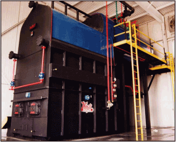
This ECM comprises the design and construction of a Biomass Cogeneration Facility
(cogeneration facility) to be located to the northwest of the main distribution steam
interconnection at the intersection of Burma Road and C Road. The steam produced from the facility
will be exported to the 200 Areas via the existing distribution system; the green power generated
will be exported to the SRS electrical distribution system via a new interconnection at the
existing F Area substation. The scope of work includes the installation of the cogeneration
facility and all equipment, the site work, and the necessary utility interconnections required for
plant operation. There are three additional items included in the scope (design drawings for these
items to be provided following contract award):
| |
1) |
|
The procurement and installation of a new skid-mounted river water pump and new pumping
systems controls at the river water pump house, Building 681-3G. |
| |
| |
2) |
|
Rework of the electrical feeder from the TNX area to the South Carolina Electric and
Gas (SCE&G) utility line at the D Area. |
| |
| |
3) |
|
Relocation of the existing L Area capacitor bank. |
The cogeneration facility will be sized to provide a continuous supply of steam to site end-users
(based on current and future load projections as presented in the SRS Site Projection Profile
provided by the Government) while optimizing the quantity of green power generated. The system is
designed using applicable national codes and standards for power plants and specific site standards
(refer to Section 5.2). Previously, conceptual design drawings were submitted to the site for
review prior to issuance of this final proposal; a draft version of the “issued for pricing”
drawings is included in Volume III of this proposal. Finalized “issued for construction” drawings
will be submitted to the government for concurrence throughout the first year of the construction
period, as major equipment items are ordered and the design drawings are finalized.
This ECM will provide an estimated savings of over $33 million in the first year of operation
through the offset of coal purchases, and reduced O&M from the elimination of the existing D Area
Power Plant and electrical substation. The renewable energy-fueled cogeneration facility will also
provide renewable energy credits (RECs) to SRS at no cost. For purposes of receiving credit for
implementing this renewable energy initiative, the RECs attached to ECM 1 and ECM 2 will belong to the Government and
will not be claimed nor sold by Ameresco.
Use or disclosure of data contained on this sheet is subject to the restriction on the first page of this proposal
|
|
|
Revised Final Proposal — May 11, 2009
Ameresco Federal Solutions
Page 5
|
|
Biomass Cogeneration Facility and Heating Plants
Savannah River Site
Contract DE-AM36-02NT41457 |
In addition to the design and construction, Ameresco will retain responsibility for fuel
delivery, operations, maintenance of the cogeneration facility and site; repair and replacement of
the cogeneration facility equipment; air and effluent outfall emissions compliance for the
cogeneration facility; and monitoring, measurement, and verification (M&V) throughout the contract
term. Refer to Section 5.2.7 for details on Ameresco’s Site Operations.
1.2.1.2 ECM Design Process
The proposed cogeneration facility will provide steam and power to the SRS site. Several
configurations and energy models were analyzed during the Detailed Energy Survey (DES) phase to
determine the final system sizing and system components. The optimal equipment selection and
sizing was selected to balance the current and future thermal needs of the site while maximizing
green power generation. Final selection resulted in a system composed of two (2) biomass bubbling
fluidized bed boilers, each with an output capacity of 120,000 PPH (240,000 PPH plant total) steam
and one (1) condensing steam turbine/generator with an output design capacity of 20 MW.
Superheated steam will be produced in the new combustor/boiler systems at 850 pounds per square
inch gauge (psig) and 825 degrees Fahrenheit (°F), for delivery to the turbine/generator
unit. Steam is extracted at a reduced pressure (385 psig nominal) from the turbine to meet the
demand of the site, as well as for parasitic use. As the primary purpose of the cogeneration
facility is to provide a continuous supply of steam, the amount of steam extracted from the turbine
will vary to meet the site demand. As the extraction rate varies with the site steam demand, the
gross power output from the turbine/generator will also vary. Based on future steam load forecasts
as presented in the SRS Site Projection Profile provided by the Government (Table 1.1 below),
output from the turbine/generator will range from 8 to 20 MW. The net power exported will vary
from 5 to 17 MW as the new cogeneration facility’s in-house (parasitic) loads will range between
2-4 MW. A detailed basis of design is included in the following subsections.
Site
The location of the new cogeneration facility was selected during the initial feasibility study of
the project. The facility will be located approximately 0.5 miles northwest of the intersection of
Burma and C Roads on a 30 acre site. The development on the site will include the following major
areas: 1) the fuel handling yard, 2) the boiler/combustion system, 3) the power plant, 4) the
cooling tower and outfall piping, and 5) the administration building and site parking. The
placement of the cogeneration facility on this site was optimized to minimize fuel handling
conveyor runs, and to ensure critical systems are located near the operator control room. The
layout was also arranged to make use of the natural topography of the land where possible to
minimize disturbance to the environment. The location and layout of the facilities were also
optimized to the extent possible with regard to interfaces with site utilities (described in
Section 1.2.3), a new storm water collection system and outfall, and the new site fire protection
system.
The storm water system is designed to collect storm water from the impervious portions of the site.
These include building run-off, roadway run-off, and equipment run-off. The system will include a
series of
Use or disclosure of data contained on this sheet is subject to the restriction on the first page of this proposal
|
|
|
Revised Final Proposal — May 11, 2009
Ameresco Federal Solutions
Page 6
|
|
Biomass Cogeneration Facility and Heating Plants
Savannah River Site
Contract DE-AM36-02NT41457 |
catch basins to collect the storm water. The site will be graded to direct the storm water to
each of the catch basins. The catch basins will be interconnected by 6”, 8”, and 12” piping. A
manhole will be included to provide maintenance access at each change of direction. Ultimately the
storm water will be directed by gravity to a storm water detention pond which is sized to hold the
expected rainfall peaks in the area. The pond will be complete with a liner and slotted spillway
to enable a controlled release of water to the outfall. The system will be installed with a
monitoring system to measure flow, pH, and conductivity. Major components include catch basins,
piping, manholes for maintenance access, lined 165,000 gallon detention pond, monitoring system,
and the 24” outfall.
Extensive soil testing was completed on the site to determine the conditions for the soil and
recommended design for structural support of equipment, facilities, and new pavements. The soil
composition is primarily sand with light clay and therefore requires treatment of the site with an
engineered fill prior to foundation work. A copy of the complete soil report is included in
Appendix A of this proposal.
Logistics of site traffic are designed to allow biomass delivery trucks and other facility traffic
to enter the site from Burma Road. The existing gravel portion of Burma Road will be paved up to
the entrance of the site. Delivery trucks will enter the facility from the Burma Road entrance
using a new deceleration lane, and exit the facility via a new one-way exit along the former route
of Old Burma Road (currently an unmaintained dirt pathway between Burma and C Roads). All other
facility traffic will enter into the new parking lot or the on-site access road, and may then exit
back to Burma Road or use the new one-way exit to C Road.
Delivery trucks will traverse the entrance road to the fuel yard, and after fuel delivery will exit
via Old Burma Road, which will be re-cleared and paved up to C Road at the existing 3-way
intersection of C Road and the entry to the F Area. Old Burma Road will be designated and marked
as a one-way thoroughfare in accordance with South Carolina Department of Transportation (SCDOT)
standards, and the traffic signal at the existing 3-way intersection on C Road will be converted to
a new 4-way intersection. This arrangement provides for a safe traffic flow and allows delivery
vehicles to make left-hand turns across traffic only at a signal-controlled intersection. Also
included in the site scope of work is the removal of the curbed median at the existing 3-way
intersection, and the installation of new loop-control vehicle sensor wiring beneath the pavement
at the new 4-way intersection. Figure 1.1 is an illustration of the overall site layout; the
specific areas within the site are further described in the following pages.
Use or disclosure of data contained on this sheet is subject to the restriction on the first page of this proposal
|
|
|
Revised Final Proposal — May 11, 2009
Ameresco Federal Solutions
Page 7
|
|
Biomass Cogeneration Facility and Heating Plants
Savannah River Site
Contract DE-AM36-02NT41457 |
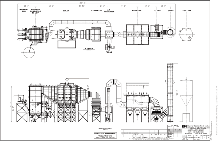
Figure 1.1: Proposed Cogeneration Facility Site Layout
[**]
Use or disclosure of data contained on this sheet is subject to the restriction on the first page of this proposal
|
|
|
Revised Final Proposal — May 11, 2009
Ameresco Federal Solutions
Page 8
|
|
Biomass Cogeneration Facility and Heating Plants
Savannah River Site
Contract DE-AM36-02NT41457 |
Fuel Handling Yard
The fuel handling yard will serve as the delivery point for all fuel supplies for the cogeneration
facility, as well as the two heating plants serving the K and L Areas. Approximately 40-60 trucks
will enter the site daily (at staggered delivery times) at the Burma Road facility entrance. The
entrance to the yard will include truck scales for weigh-in of all fuel sources for tracking
deliveries. Beyond the entrance will be the unloading equipment, fuel storage area, and the fuel
handling and processing equipment.
For fuel handling operations at the cogeneration facility, front-end loaders and augers/conveyors
will be used at various points in the yard to move fuel between stations, through the yard area,
and into the combustion systems. The biomass wood fuel will be unloaded using three (3) automated
hydraulic truck-dumping stations. The truck-dumpers discharge into a reclaim pit, where the fuel
will be lifted to the first transfer conveyor. The fuel is then screened and processed through a
hogger and disc screen onto a second transfer conveyor. The fuel can then be transferred into the
outside storage area or directly into the metering bins of the combustors. Stored fuel will be
stacked in the outside storage after delivery from the transfer conveyor by use of a circular
stacker/reclaimer. In addition to stacking the fuel, the stacker/reclaimer functions as a
reclaimer to transfer the fuel from the storage stack to the fuel metering bins prior to entering
the combustors.
The total available outside storage for clean biomass is approximately 15 acres, allowing for 30
days of continuous operations without replenishing the on-site fuel storage. The scrap vehicle
tires brought to the site will be unloaded and processed in a separate area before being augured
into a separate reclaimer. The separate unloading area and reclaimer allow for better process
control through mixing with the biomass fuel, and also help to quantify BDF usage in meeting the
requirements of the South Carolina Department of Health and Environmental Control (SCDHEC) air
permit with regards to limits on BDF combustion.
Fuel supplies for the K and L Area boilers will be loaded at the cogeneration facility fuel
handling yard and trucked by Ameresco staff to the K and L Area heating plants as needed, since the
heating plants operate only during a limited heating season. One truckload per day is the
estimated maximum usage at both the K and L Area heating plants during the coldest periods.
Proposed Fuel Yard Components include:
| |
• |
|
Two (2) Truck scales |
| |
| |
• |
|
Three (3) Hydraulic truck dumps and reclaimers |
| |
| |
• |
|
Front end loaders |
| |
| |
• |
|
Dump trucks for site use |
| |
| |
• |
|
Live bottom trailers for K and L Area |
| |
| |
• |
|
One (1) Fuel hogger |
| |
| |
• |
|
One (1) Screener for oversized product |
| |
| |
• |
|
Two (2) Magnets for metals screening |
| |
| |
• |
|
One (1) Stacker & Reclaimer |
| |
| |
• |
|
One (1) Truck Reclaim for Tires |
Use or disclosure of data contained on this sheet is subject to the restriction on the first page of this proposal
|
|
|
Revised Final Proposal — May 11, 2009
Ameresco Federal Solutions
Page 9
|
|
Biomass Cogeneration Facility and Heating Plants
Savannah River Site
Contract DE-AM36-02NT41457 |
| |
• |
|
One (1) Shredder for tires |
| |
| |
• |
|
Multiple conveyors for fuel handling |
| |
| |
• |
|
One (1) Whole Tree Chipper |
The final design of the system was developed with primary consideration given to the
following: handling and processing of multiple fuel types; safe and plentiful fuel storage area on
site; minimized maintenance requirements; reduced downtimes; and provision for flexible operation
of the overall systems.
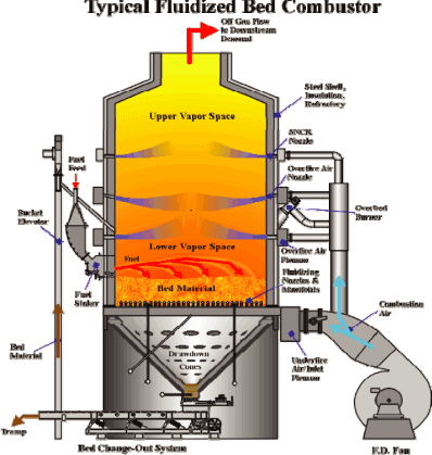
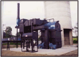
Combustion/Boiler System
The combustion/boiler system includes the components from the fuel feeders to the exhaust stack,
including the boiler auxiliaries. A bubbling fluidized bed (BFB) combustion technology will be
used for this project. BFB technology uses high pressure air to fluidize a 2-3 foot bed of sand
(inert material) in suspension. The fuel source is fed into the system through air spouts and
mixed into the suspended bed. The system operates using 30-40% theoretical combustion air to
reduce bed temperature and minimize nitrogen oxide (NOx) emissions.
BFB technology is preferable for biomass fuels due to its ability to better tolerate various fuel
types, as well as larger variations in both fuel mixture density and moisture content. BFBs have
the advantage of reduced air emissions due to a more stringently controlled temperature in the
combustion process (1400-1600oF). Compared to stoker technology, the bubbling bed
offers lower uncontrolled air emission rates, resulting in a lower investment for downstream air
pollution control system components. BFBs require less maintenance than the stoker boiler,
resulting in less downtime and lower ongoing costs.
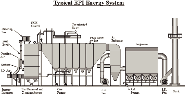
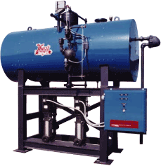
[**]. The EPI system is shown in Figure 1.2. The EPI combustor/boiler offers the following
benefits in this size range of BFB equipment:
[**]
Use or disclosure of data contained on this sheet is subject to the restriction on the first page of this proposal
|
|
|
Revised Final Proposal — May 11, 2009
Ameresco Federal Solutions
Page 10
|
|
Biomass Cogeneration Facility and Heating Plants
Savannah River Site
Contract DE-AM36-02NT41457 |
Figure 1.2: EPI Fluidized Bed Energy System
Two identical BFBs will be installed in the new cogeneration facility. Both boilers will be sized
for a total design input of 372 MBtu/hr (186 MBtu/hr per boiler) and an output of 240 kpph (120
kpph per boiler). The bubbling bed boiler will produce steam at 850 psig, 825°F. Steam
generated will go through a condensing turbine when generating electricity, or through a pressure
reducing valve (PRV) station which will reduce the pressure to 385 psig. Steam required by the
site and for the cogeneration facility deaerator (DA) tank will be extracted from the turbine at
385 psig. The 385 psig steam will be distributed to the existing system via the interconnection to
the existing steam header located just across the street from the new cogeneration facility.
Additionally, full capacity fuel oil burners will also be installed in the combustor to serve as a
back up fuel source in case the biomass feeders are down. Refer to Section 1.2.1.3 for details of
SRS steam demand.
Use or disclosure of data contained on this sheet is subject to the restriction on the first page of this proposal
|
|
|
Revised Final Proposal — May 11, 2009
Ameresco Federal Solutions
Page 11
|
|
Biomass Cogeneration Facility and Heating Plants
Savannah River Site
Contract DE-AM36-02NT41457 |
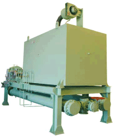
Figure 1.3: EPI Fluidized Bed Cell
Fuel will enter into the combustion metering bins from the fuel transfer conveyors. Metered fuel
is discharged through isolation slide gates and into the fuel spreaders. The spreaders distribute
the fuel across the fluidized bed. The fluidized bed cell as shown in Figure 1.3 includes the
equipment to accept, distribute, and mix air, fuel, and limestone in a high temperature thermal
oxidization environment. The system is designed in accordance with National Fire Protection
Association (NFPA) Section 850. Underbed air and overfire air distribution systems are provided to
allow proper air flow for uniform combustion, to provide cooling of tramp material, and to optimize
overall bed temperature.
The EPI system is specifically designed to include a bed recycle system to accommodate wood and
tire derived fuel containing wires. The tire bed system is a fluidizing bed bottom, wire
separation, and screening system designed to handle high concentrations of wire left over from the
thermal oxidization of shredded tires and tramp material. The metal is recovered from the rest of the tramp material and
bed media then discharged to the hopper for recycling.
Use or disclosure of data contained on this sheet is subject to the restriction on the first page of this proposal
|
|
|
Revised Final Proposal — May 11, 2009
Ameresco Federal Solutions
Page 12
|
|
Biomass Cogeneration Facility and Heating Plants
Savannah River Site
Contract DE-AM36-02NT41457 |
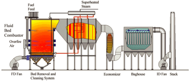
Each of the biomass boilers will include a gas handling system, which includes an induced
draft (ID) fan to pull the boiler flue gas through the economizer. The ID fan exhausts into a
fabric filter baghouse and then to an integral exhaust stack.
Pollution Abatement Control
The fluidized bed system provides an environment to optimize destruction of hazardous air
pollutants and volatile organic compounds. Additional pollution abatement control is included in
this system to comply with air emission requirements.
Particulate Matter Control: Particulate in the gas stream is captured in a pulse-jet baghouse
system. The baghouse captures particulate matter from the flue gas and has removal efficiencies of
99.9+%. The flue gas will then exit through a stack adjacent to the ID fan and baghouse located
just outside of the new cogeneration facility.
Nitrogen Oxide Control: The flue gas from the boiler will be treated in the combustion system
using selective non-catalytic reduction (SNCR) technology to reduce nitrogen oxides. Using the
SNCR will reduce NOx rates to 0.12 lb/MBtu. Urea is injected into the furnace typically above the
over-fire air ports, reacting with the oxides to form nitrogen and hydrogen.
Sulfur Dioxide Control: Since tire derived fuel will be used as a fuel source, each biomass boiler
will also have a bed additive system. The bed additive system will introduce limestone into the
fluidized bed cells in order to reduce sulfur dioxide and other acid emissions. Sulfur dioxide
will be controlled to less than 0.2 lb/MBtu in order to comply with air permit conditions.
Each boiler will include an exhaust stack. Each stack will include an aviation lighting system,
and a continuous emissions monitoring system to measure the stack emissions and provide data
reporting. The system will monitor carbon monoxide (CO), oxygen (O2), NOx,
SO2, reagent slip, and opacity. The data is recorded in the facility supervisory
control and data acquisition (SCADA) system.
Ash Handling System
The fuel will primarily consist of clean biomass sources; therefore, the ash content is expected to
be low, less than 1.0-3.0% of the fuel burned. The ash stream consists of a bottom ash stream and
a flyash stream. Bottom ash will be automatically removed from the biomass boiler with mechanical
conveyors and augered into a hopper outside of the building. Fly ash will be collected at multiple
points along the flue gas exhaust train, including boiler hoppers, mechanical dust collector
hoppers, and baghouse. The flyash system will be a mechanical pneumatic system consisting of
rotary air-lock valves, screw conveyors, drag conveyors, and storage container. The ash collection
hoppers will include water nozzles to keep ash wet and minimize dusting into the plant area.
The ash generated from combustion will be delivered to the landfill or taken off site to potential
end-users. Ameresco will be responsible for ash removal, and the cost is included in the
performance period expenses.
Use or disclosure of data contained on this sheet is subject to the restriction on the first page of this proposal
| |
|
|
|
Revised Final Proposal — May 11, 2009
|
|
Biomass Cogeneration Facility and Heating Plants |
Ameresco Federal Solutions
|
|
Savannah River Site |
Page 13
|
|
Contract DE-AM36-02NT41457 |
Major Combustion/Boiler System Components:
| |
• |
|
Two (2) 120,000 PPH biomass fluidized bed boilers, including fan systems |
| |
| |
• |
|
Two (2) Baghouses including Penthouse |
| |
| |
• |
|
Two (2) SNCR systems (Urea Injection) |
| |
| |
• |
|
Boiler auxiliaries (boiler feed water pumps, DA tank, chemical treatment, and
instrumentation) |
| |
| |
• |
|
Boiler control SCADA system |
| |
| |
• |
|
Two (2) Ash bins |
| |
| |
• |
|
Two (2) Ash storage silos |
| |
| |
• |
|
Two (2) Ash conveying systems (for each biomass boiler) |
| |
| |
• |
|
Fuel Oil Storage |
| |
| |
• |
|
Reagent Storage |
| |
| |
• |
|
Limestone Storage |
Power Plant
The power plant will house the boiler feedwater system, the water treatment system, the chemical
treatment system, and the steam condensing turbine. The cooling tower and emergency generators
will be located outside to the west of the power plant. The building will be a pre-engineered
two-tiered metal building and 16,000 sq ft in size. Within the power plant there will be a control
room, break room, storage, chemical and sampling area, and the motor control center. The equipment
components are described in the sections below.
Boiler Feedwater System
A feedwater system will pressurize and deliver deaerated boiler feedwater from the DA tanks and the
desuperheater to the boilers. The boiler feed pumps will pull the heated water from the DA tanks.
Since there is no condensate return infrastructure in place, the DA tanks will receive makeup water
from the water treatment system and from the condensate tank. The feedwater will be delivered to
the boiler at 850 psig and 370oF. There are 2 DA tanks for the boilers; one will be
used as a backup.
Components of the primary feedwater system include the following:
| |
• |
|
Three (3) Boiler feed pumps and motors |
| |
| |
• |
|
Two (2) DA tanks with instrumentation and trim |
| |
| |
• |
|
Piping, valves, and controls |
Water Treatment System
River water will be used as the source of water for the process water, regeneration water, and for
fire system water. The river water will be filtered through carbon filters and softeners. Process
water will be treated using Reverse Osmosis (RO) technology and then deionized through a mixed bed
system. This system was designed based on samples collected from the Savannah River during the DES
and from water analysis reports for the D-Area plant. The peak make-up requirement to the
cogeneration facility is
Use or disclosure of data contained on this sheet is subject to the restriction on the first page of this proposal
| |
|
|
|
Revised Final Proposal — May 11, 2009
|
|
Biomass Cogeneration Facility and Heating Plants |
Ameresco Federal Solutions
|
|
Savannah River Site |
Page 14
|
|
Contract DE-AM36-02NT41457 |
2,200 gallons per minute (gpm); this would occur at the cogeneration facility’s full capacity and
if the water treatment regeneration cycles were occurring at the same time. Normal flow rate to
the water treatment skid will be 600 gpm. Primary components of the water treatment system
include:
| |
• |
|
Four (4) Carbon Filters |
| |
| |
• |
|
Two (2) Water Softeners |
| |
| |
• |
|
Neutralization Tank |
| |
| |
• |
|
RO System |
| |
| |
• |
|
Two (2) Deionized Mixed Beds |
| |
| |
• |
|
Neutralization Skid |
| |
| |
• |
|
Deionized Water Storage Tank |
Chemical Feed System
Chemical feed systems are designed for the boilers to provide protection from corrosion, scale
formation, circulating water biofouling, and to provide pH control. Specific internal boiler water
treatment programs will be designed during the implementation phase. Chemical equipment includes
the following:
| |
• |
|
Internal Boiler Water Treatment: Chemical feed skid(s) with injection
pumps. The skid will be pre-piped, pre-wired, including necessary components and
accessories for a complete functional system. Feed skid to be used with chemical
totes. |
| |
• |
|
Circulating Water System |
| |
• |
|
Common acid chemical feed skid with injection pumps, pre-piped, pre-wired
and including necessary components and accessories for a complete functional system.
Feed skid to be used with chemical totes. |
| |
| |
• |
|
Corrosion control chemical feed skid with injection pumps (dispersant and
corrosion inhibitor), pre-piped, pre-wired and including necessary components and
accessories for a complete functional system. Feed skid to be used with chemical
totes. |
| |
| |
• |
|
Biocide chemical feed skid with injection pumps, pre-piped, pre-wired and
including necessary components and accessories for a complete functional system. Feed
skid to be used with chemical totes. |
Turbine System
The turbine will be installed in the power plant building. The turbine generator will have a rated
output of 20 MW and generate at 13.8 kilovolts (kV). The turbine will be provided by TGM;
information on the TGM system is included in Appendix C. The TGM turbine is manufactured in
Brazil; however, Ameresco selected it for the SRS project because of its higher efficiency, lower
cost, and shorter delivery time. Ameresco requested and the contracting officer has added the TGM
turbine to the exemption list for Buy American.
Use or disclosure of data contained on this sheet is subject to the restriction on the first page of this proposal
| |
|
|
|
Revised Final Proposal — May 11, 2009
|
|
Biomass Cogeneration Facility and Heating Plants |
Ameresco Federal Solutions
|
|
Savannah River Site |
Page 15
|
|
Contract DE-AM36-02NT41457 |
Electrical Generation Equipment:
| |
• |
|
One (1) TGM Steam Condensing Turbine (20 MW), Model TMCE 25000A |
| |
| |
• |
|
Electrical switchgears |
| |
| |
• |
|
Two (2) fuel oil-fired emergency generators (1.5 MW each) |
| |
| |
• |
|
Surface Condenser |
| |
| |
• |
|
High Voltage, Medium Voltage Transformers |
Cooling System
| |
• |
|
One (1) two-cell Cooling Tower with variable frequency drive (VFD) Fans |
| |
| |
• |
|
Cooling Tower pumps |
| |
| |
• |
|
Outfall Sampling Station |
Administration Area
A 2,200 sq ft building will be constructed to provide office space for cogeneration facility
management staff and to also provide an area to allow visitors to gather for facility tours.
Fire Protection Plan
The Site Fire Protection Plan includes different methods depending on the type of area and the
recommended practice for fire protection. The site will include a stationary pump as well as the
following elements described below.
Biofuel receiving and storage areas
| |
• |
|
NFPA 850, Recommended Practice for Fire Protection for Electric Generating Plants |
| |
• |
|
Fire water loop with hydrants and post indicating valves installed in
accordance with NFPA 24 Standard for the Installation of Private Fire Service Mains and
Their Appurtenances |
| |
• |
|
International Fire Code |
| |
• |
|
Open access for emergency vehicles |
Boiler/Turbine/Equipment yard
| |
• |
|
NFPA 850, Recommended Practice for Fire Protection for Electric Generating Plants |
| |
• |
|
Fire water loop with hydrants and post indicating valves installed in
accordance with NFPA 24 Standard for the Installation of Private Fire Service Mains and
Their Appurtenances |
| |
• |
|
International Fire Code |
| |
• |
|
Open access for emergency vehicles |
Turbine Hall
| |
• |
|
NFPA 850, Recommended Practice for Fire Protection for Electric Generating Plants |
| |
• |
|
Oil containment/drainage system |
Use or disclosure of data contained on this sheet is subject to the restriction on the first page of this proposal
| |
|
|
|
Revised Final Proposal — May 11, 2009
|
|
Biomass Cogeneration Facility and Heating Plants |
Ameresco Federal Solutions
|
|
Savannah River Site |
Page 16
|
|
Contract DE-AM36-02NT41457 |
| |
• |
|
A hose connection |
| |
| |
• |
|
Fixed protection system, detection, and alarm system to cover, as minimum,
the Turbine/Generator bearings and oil containment areas. |
| |
| |
• |
|
Turbine shut down control per NFPA 850 |
Administration Area
| |
• |
|
International Building Code and International Fire Code |
| |
• |
|
Detection, alarm, and sprinkler system installed in accordance with NFPA
13 Standard for the Installation of Sprinkler Systems and NFPA 72 National Fire Alarm
Code |
Lab, Breakroom, and Bathrooms
| |
• |
|
International Building Code and International Fire Code |
| |
• |
|
Detection, alarm, and sprinkler system installed in accordance with NFPA
13 Standard for the Installation of Sprinkler Systems and NFPA 72 National Fire Alarm
Code |
Control Room and Electrical Rooms
| |
• |
|
NFPA 850, Recommended Practice for Fire Protection for Electric Generating Plants |
| |
• |
|
Detection and alarm system installed in accordance with NFPA 72 National
Fire Alarm Code |
| |
• |
|
Detection, alarm, and fixed protection under raised floors. |
| |
• |
|
Fixed protection — Dry Chemical, NFPA 17 |
Biofuel Conveyors and Transfer Towers
| |
• |
|
NFPA 850, Recommended Practice for Fire Protection for Electric Generating Plants |
| |
• |
|
Protection, detection, and alarm systems are not required but are a good practice |
| |
• |
|
Dry type deluge system install in accordance with NFPA 13 Standard for
the Installation of Sprinkler Systems |
| |
• |
|
Detection and alarm system installed in accordance with NFPA 72 National
Fire Alarm Code |
| |
• |
|
Conveyor controls to be interlocked per NFPA 850 |
Cooling Tower
| |
• |
|
NFPA 850, Recommended Practice for Fire Protection for Electric Generating Plants |
| |
• |
|
Hydrant installed in accordance with NFPA 24 Standard for the Installation
of Private Fire Service Mains and Their Appurtenances |
| |
• |
|
Cooling Tower design and constructed in accordance with NFPA 214, Standard
on Water-Cooling Towers |
Fuel Oil Storage Tank
| |
• |
|
NFPA 30: Flammable and Combustible Liquids Code |
| |
• |
|
Separation in accordance with NFPA 30 |
| |
| |
• |
|
100% containment in accordance with NFPA 30 |
Use or disclosure of data contained on this sheet is subject to the restriction on the first page of this proposal
| |
|
|
|
Revised Final Proposal — May 11, 2009
|
|
Biomass Cogeneration Facility and Heating Plants |
Ameresco Federal Solutions
|
|
Savannah River Site |
Page 17
|
|
Contract DE-AM36-02NT41457 |
| |
• |
|
Design and construction in accordance with NFPA 30 |
| |
• |
|
Hydrant installed in accordance with NFPA 24 Standard for the Installation
of Private Fire Service Mains and Their Appurtenances |
1.2.1.3 ECM 1 Operation
ECM 1 will be operated continuously to produce steam and power for SRS, with the primary
mission of meeting the Annual Steam Guarantee (ASG). The ASG is the total amount of steam output
from the biomass boilers as defined in Section 1.2.7.4. During normal operation, steam produced
from the boilers will flow through the condensing steam turbine. Steam required for the
cogeneration facility auxiliaries and the export steam required by the site will be extracted from
the turbine. The balance of steam will continue through the turbine to generate additional green
power. As required by SRS, the cogeneration facility will be operated to provide steam at 350 psia
through the existing Government-owned distribution system to the users in the F and H Areas.
Scheduled outages will not exceed one per year and only one boiler will be taken down at a time for
planned maintenance. In the unlikely event that both boilers are inoperable, Ameresco has made
provisions and connections for bringing temporary boilers to the site to ensure the supply of
steam.
Projected steam demands of the site are based on information provided in the SRS Site Projection
Profile provided by Government personnel. The projections upon which the cogeneration facility
performance model is based was provided by government personnel in the SRS Site Projection Profile
and shows that annual steam loads will differ for the next 20 years as shown in Table 1.1. Due to
these changes in operation and the anticipated variation in weather from year to year, it is
proposed that the new cogeneration facility will be operated to produce a fixed quantity of steam
each year, the ASG. As the demand for exported steam decreases, the amount of green power
generation will increase, up to the ASG.
Table 1.1: SRS Site Projection Profile — Steam Demand
| |
|
|
|
|
|
|
| |
|
Winter peak |
|
Winter average |
|
Summer average |
| Year |
|
[kpph] |
|
[kpph] |
|
[kpph] |
2009
|
|
[**]
|
|
[**]
|
|
[**] |
2010
|
|
[**]
|
|
[**]
|
|
[**] |
2011
|
|
[**]
|
|
[**]
|
|
[**] |
2012
|
|
[**]
|
|
[**]
|
|
[**] |
2013
|
|
[**]
|
|
[**]
|
|
[**] |
2014
|
|
[**]
|
|
[**]
|
|
[**] |
2015
|
|
[**]
|
|
[**]
|
|
[**] |
2016
|
|
[**]
|
|
[**]
|
|
[**] |
2017
|
|
[**]
|
|
[**]
|
|
[**] |
2018
|
|
[**]
|
|
[**]
|
|
[**] |
2019
|
|
[**]
|
|
[**]
|
|
[**] |
Use or disclosure of data contained on this sheet is subject to the restriction on the first page of this proposal
| |
|
|
|
Revised Final Proposal — May 11, 2009
|
|
Biomass Cogeneration Facility and Heating Plants |
Ameresco Federal Solutions
|
|
Savannah River Site |
Page 18
|
|
Contract DE-AM36-02NT41457 |
Table 1.1: SRS Site Projection Profile — Steam Demand
| |
|
|
|
|
|
|
| |
|
Winter peak |
|
Winter average |
|
Summer average |
| Year |
|
[kpph] |
|
[kpph] |
|
[kpph] |
2020
|
|
[**]
|
|
[**]
|
|
[**] |
2021
|
|
[**]
|
|
[**]
|
|
[**] |
2022
|
|
[**]
|
|
[**]
|
|
[**] |
2023
|
|
[**]
|
|
[**]
|
|
[**] |
2024
|
|
[**]
|
|
[**]
|
|
[**] |
2025
|
|
[**]
|
|
[**]
|
|
[**] |
2026
|
|
[**]
|
|
[**]
|
|
[**] |
2027
|
|
[**]
|
|
[**]
|
|
[**] |
2028
|
|
[**]
|
|
[**]
|
|
[**] |
2029
|
|
[**]
|
|
[**]
|
|
[**] |
2030
|
|
[**]
|
|
[**]
|
|
[**] |
2031
|
|
[**]
|
|
[**]
|
|
[**] |
Ameresco staff will be responsible for operating and maintaining the cogeneration facility
throughout the contract term as detailed in Section 5.2.7.1, and the cogeneration facility will be
continuously manned by Ameresco staff as described in Section 5.2.7. However, this Final Proposal
excludes any operation and maintenance obligations on the part of Ameresco except as detailed in
Section 5.2.7.1
1.2.2 Location Affected
During the Initial Proposal kickoff meeting, the Government presented three sites as potential
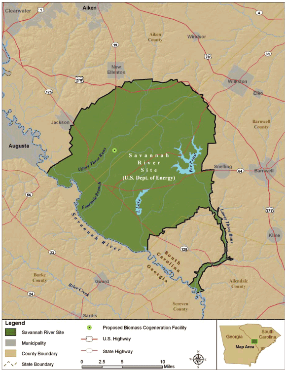
locations for the new cogeneration facility. The selected site is shown in Figure 1.4 below and
was agreed upon by SRS, the M&O Contractor, and Ameresco based on an evaluation of many factors,
including distance to existing utility connections, available acreage, accessibility, security
concerns, and environmental impacts. A site-use permit was obtained and is currently being amended
to include the electrical feeder to the F Area, the river water piping tie-in from the C Area, the
process water outfall to Upper Three Runs Creek, and improvements to the Old Burma Road/C Road
intersection.
Use or disclosure of data contained on this sheet is subject to the restriction on the first page of this proposal
| |
|
|
|
Revised Final Proposal — May 11, 2009
|
|
Biomass Cogeneration Facility and Heating Plants |
Ameresco Federal Solutions
|
|
Savannah River Site |
Page 19
|
|
Contract DE-AM36-02NT41457 |
Figure 1.4: Cogeneration Facility Site Location
Use or disclosure of data contained on this sheet is subject to the restriction on the first page of this proposal
|
|
|
Revised Final Proposal – May 11, 2009
Ameresco Federal Solutions
Page 20
|
|
Biomass Cogeneration Facility and Heating Plants
Savannah River Site
Contract DE-AM36-02NT41457 |
1.2.3 ECM 1 Interface with Government Equipment
Title to all Ameresco installed equipment will transfer to the Government at the time of
Government acceptance of an ECM. Title to the biomass fuel will transfer to and vest in the
Government simultaneously with Ameresco’s receipt of the biomass at the fuel handling yard. For the
sake of clarity, ECM 1 will interface with existing Government equipment at the utility
interconnections as described in this section. The installation of utility interconnections
required for the new cogeneration facility are included in the project implementation cost and the
installation will be Ameresco’s responsibility; however, the SRS M&O Contractor will retain O&M
responsibility including repair and replacement for the utility interconnections and utility
distribution systems. Table 1.2 provides a summary of the utility interface and the scope of O&M
responsibility for the utility systems. Ameresco and the SRS M&O Contractor will enter into an
agreement that will provide the cogeneration facility with utility services to include river water,
sanitary sewer service, backup electrical power, and domestic water service. A Power Services
Utilization Permit (PSUP) form will be completed by Ameresco prior to construction of utility
interconnections. Utility meters will be installed to measure usage. It is proposed the
Government will incur the cost for the cogeneration facility’s non fuel utilities. These Post-ECM
Implementation Costs have been factored into the annual savings. The annual consumption and costs
of the utilities are shown in Table 1.6, and the unit cost used for each utility is shown in Table
4.2. Refer to Section 5.2.7.1 for operation and maintenance responsibility.
Infrastructure services (site facility operations and maintenance) are primarily the responsibility
of the Site M&O Contractor. M&O Contractor personnel operate and maintain the SRS utility systems
and manage site environmental programs. On site DOE personnel are charged with oversight of M&O
Contractor operations although M&O Contractor personnel often render project or program decisions
for the Government. Therefore, for purposes of this proposal, the use of the term “Government” is
applicable to DOE and M&O Contractor. For example, the term “Government caused delays” includes
any delays caused by government and/or M&O Contractor personnel. Although the M&O Contractor makes
operational decisions for the systems they operate and programs they manage, only DOE personnel,
i.e. Contracting Officer and Contracting Officer’s Representative (COR) will provide project and
program decisions affecting work performed by Ameresco or Ameresco subcontractor personnel
resulting from this proposal.
Table 1.2: Utility Interconnection Summary
| |
|
|
|
|
| Utility |
|
Interconnection |
|
O&M Responsibility |
Steam
|
|
New 12”, 240 kpph
line from plant to
existing 24” across
Burma Road
|
|
Ameresco: To the point of the new valve
located in a new 12” line near the point of
interconnection (POIC) with the existing steam
line. SRS: Upstream of the new valve. |
|
|
|
|
|
Domestic Water
|
|
30 gpm, new 2” line
from plant to
header located
outside existing
water treatment
plant
|
|
Ameresco: To the new utility valve outside of
power plant. SRS: Downstream of the tie-in
to the new valve. |
Use or disclosure of data contained on this sheet is subject to the restriction on the first page of this proposal
|
|
|
Revised Final Proposal – May 11, 2009
Ameresco Federal Solutions
Page 21
|
|
Biomass Cogeneration Facility and Heating Plants
Savannah River Site
Contract DE-AM36-02NT41457 |
Table 1.2: Utility Interconnection Summary
| |
|
|
|
|
| Utility |
|
Interconnection |
|
O&M Responsibility |
River Water
|
|
New 12",2200 gpm
line from valve
house near C-Area
to new biomass
plant
|
|
Ameresco: Downstream of the interconnection
valve. SRS: From existing pump station up to
interconnection valve at cogeneration
facility. |
|
|
|
|
|
Outfall
|
|
1200 gpm + storm
water runoff, new
24" line to Upper
Three Runs Creek
|
|
Ameresco: To conduct all testing of the
effluent; responsible for maintaining
compliance of this discharge. |
|
|
|
|
|
Sanitary Sewer
|
|
New 4" line & new
lift station, 20
gpm to upside of
the existing Lift
Station
|
|
Ameresco: To the new valve located in the new
line outside of power plant.
SRS: Downstream of the new utility valve. |
|
|
|
|
|
Electrical
|
|
New 13.8 kV line
to/from F Area
substation
|
|
SRS: From outside of new cogeneration facility |
|
|
|
|
|
Fire Water System
|
|
Tapped off the new
river water header,
prior to cooling
tower
|
|
Ameresco: Responsible for fire water system |
|
|
|
|
|
Telephone
Line/Public Address
(PA) System
|
|
Verizon New Line
|
|
Verizon/Ameresco |
|
|
|
|
|
Data Line
|
|
Verizon New Line
|
|
Verizon/Ameresco |
Steam Distribution System
Steam produced from the boiler at 850 psig and 825°F will flow through the turbine, or
through a pressure reducing valve (PRV) and desuperheater if the turbine is not operating. From
the turbine or PRV, the steam will be exported to the SRS distribution system, with a small
percentage going to the cogeneration facility DA tanks. Flash steam from the continuous blowdown
flash tank is supplied to a low pressure header to supplement the steam requirements of the DA.
The steam exported to the distribution system will be delivered at 350 psig 450oF. A
new 12” carbon steel pipe will be routed above-ground from the cogeneration facility (exiting from
the turbine or PRV station) to the existing steam line located across Burma Road. A steam meter
will be installed in the line to measure steam exported from the cogeneration facility, as well as
a steam meter on the flow exiting the boilers to measure the total amount of steam produced. The
new cogeneration facility export connection is approximately 3 miles closer to the F and H Areas
than the existing D Area plant, providing increased distribution system efficiency from decreased
line losses. The approximate point of interconnection is shown in the photograph below:
Figure 1.5: Biomass Cogeneration Facility Steam Interconnection
[**]
Domestic Water
A 2” domestic water line will be installed to serve plant potable water needs such as bathrooms,
utility sinks, showers, and eye wash stations. The new water line will connect to the existing
domestic water
Use or disclosure of data contained on this sheet is subject to the restriction on the first page of this proposal
|
|
|
Revised Final Proposal – May 11, 2009
Ameresco Federal Solutions
Page 22
|
|
Biomass Cogeneration Facility and Heating Plants
Savannah River Site
Contract DE-AM36-02NT41457 |
header located outside of the nearby industrial water treatment plant, located
approximately 0.3 miles east of the cogeneration facility. Domestic water usage is expected to be
minimal (5-10 gpm) and used for sink, lavatory, and maintenance requirements. Annual consumption
is expected to be approximately 2600 kilogallons (kgal). The domestic water interconnection will
be designed per M&O standards and permitted as required by the SCDHEC.
Process Water
River water will be used as the water source for all process and fire water. The process water
usage includes boiler feedwater, cooling tower makeup water, water treatment regeneration cycles,
and cogeneration facility service water. The river water will be supplied from Building 681-3G,
the water pump house, through an existing distribution system and pump station. A new 12” ductile
iron line will be routed underground from the existing C Area valve house (refer to Figure 1.6) to
the cogeneration facility site following the route of the abandoned steam line from the C Area, and
then diverting off of the route through existing vegetated areas to the site. Routing through the
vegetated area will reduce the new distribution pipe route by approximately 1/2 mile. The specific
routing is shown on the site drawing which is included in the drawing package (Volume III). The
peak make-up requirement to the site is 2200 gpm; this would occur if the system was operating at
full capacity and if all the regeneration cycles of the water treatment system were occurring at
the same time. Normal operations will use 600 gpm. Annual river water consumption will average
around 450,000 kgal.
To ensure there is adequate redundancy and back-up for the site river water source, in addition to
the installation of the new distribution line a new pump skid (identical to the P-10 skid) will be
installed to replace the pump, P-4, located inside the water pump house (Bldg 681-3G). The new
pump will be used as a backup for P-10 and be designed with a 19.8” impeller size (600 hp motor.)
Other components to be installed with the new pump include:
| |
• |
|
Rework of the existing suction pipe |
| |
| |
• |
|
Installation of isolation valve in suction pipe |
| |
| |
• |
|
Installation of flow control valve & flow meter |
| |
| |
• |
|
Installation of instrumentation and valves setup (duplicate system to the P-10 skid) |
| |
| |
• |
|
Control modification to allow the pumps to automatically operate based on
system requirements |
Figure 1.6: Biomass Cogeneration Facility River Water Interconnection
[**]
Site Outfall
A new 24” high density polyethylene pipe will be routed from the cooling tower basin to Upper Three
Runs Creek. The pipe will be installed underground and follow the natural topography of the land.
A new outfall structure will be constructed next to the cooling tower to allow for flow monitoring
and effluent testing. Process waste water and the storm water runoff will be discharged to the
outfall. The storm water system includes collection piping to catch basins which will divert the
storm water to the site
Use or disclosure of data contained on this sheet is subject to the restriction on the first page of this proposal
|
|
|
Revised Final Proposal – May 11, 2009
Ameresco Federal Solutions
Page 23
|
|
Biomass Cogeneration Facility and Heating Plants
Savannah River Site
Contract DE-AM36-02NT41457 |
retention pond. The retention pond will discharge to the outfall. The outfall will be
permitted under the site National Pollutant Discharge Elimination System (NPDES) permit.
Sanitary Sewer
The bathrooms and fixtures located in the cogeneration facility and in the administration building
will connect to the existing sanitary sewer system via a 4” polyvinyl chloride (PVC) pipe and be
pumped using a new lift station. The line will connect upstream to the 607-91G lift station
located approximately 0.3 mile east of the cogeneration facility. The sanitary sewer
interconnection will be designed per M&O standards and permitted as required by the SCDHEC. Annual
discharge is expected to be 2,600 kgal.
Electrical System
Power will be delivered to the existing F Area substation at 13.8 kV from the cogeneration
facility. The power feeder from the cogeneration facility will be approximately 7,600 feet and
will be routed in a combination of overhead pole mounted transmission line and underground duct
bank where required in the F Area. The feeder will connect to an existing spare breaker cell in
the metal-clad switchgear lineup at 251-F. The breaker cell shall be unit 101A, 101B, 206A, or
206B as deemed suitable by Ameresco and the Government. The interconnection scope of work includes
a compatible circuit breaker, multifunction utility-grade numerical relay and instrumentation, and
a 15kV class line potential transformer (PT) (either outdoor on feeder or indoor in a top-hat
structure added to the existing switchgear). Existing bus PT secondary sources and existing
station direct current (DC) battery sources are to be tapped as-is without improvement. Ameresco
will utilize as-is or improve existing lockout relays and circuit breaker auxiliary contacts where
no spare contacts or similar status points are available. Where such improvements are not possible
due to the limitations of existing equipment, Ameresco will propose a solution to the Government
(e.g. interposing relays, SCADA outputs, etc.). Ameresco assumes that the subject devices either
as existing or improved, sufficiently indicate the operation of distribution and transmission level
switching to determine when the generation system is unintentionally islanded from the utility
source.
Where transfer trip capability is required or determined to be best practice for protection of the
proposed generation system, transfer trip facilities are to be derived from existing utility
protective relaying equipment installed at 251-F. The scope excludes special or upgraded SCADA
communications between 251-F and electrical utility operator. This scope is limited to the feeder
circuit breaker at 251-F used to service the proposed generator plant and the primary protection
described. The scope does not include other feeders at 251-F or any other upstream devices that
are not impacted by the project (e.g. transformer secondary or primary protective devices and
features, transmission-level protective devices and features). To insure appropriate coordination
with the existing F area electrical distribution equipment, SRS will need to supply required
load-flow, short-circuit, and intertie relay settings. Ameresco will prepare a transient
study if deemed necessary for design.
Power at the new cogeneration facility is generated at 13.8 kV and is connected to a main 13.8
kV switchgear unit identified as “HVS”. “HVS” is equipped with six (6) breakers. Breaker “52G” is
utilized for the main generator breaker and is complete with required protective and synchronizing
relaying. Breaker “52-4160” feeds a 7500/9375 kilovolt amperes (KVA) transformer “ATX-2” that
steps down to 4160 volts alternating current (VAC) for large motor loads. Breaker “52-480” feeds a
2500/333 KVA
Use or disclosure of data contained on this sheet is subject to the restriction on the first page of this proposal
|
|
|
Revised Final Proposal – May 11, 2009
Ameresco Federal Solutions
Page 24
|
|
Biomass Cogeneration Facility and Heating Plants
Savannah River Site
Contract DE-AM36-02NT41457 |
transformer “ATX-1” that steps down to 480 VAC for all the remaining facility power
distribution loads. Breakers “52-SG-1” and “52-SG-2” are utilized as feeders from two 1500 kW
standby generators. Breaker “52U” is the tie breaker that feeds power to and from the F Area.
This breaker will also be complete with all required protective and synchronizing relaying. The
13.8kV switchgear “HVS” and transformers “ATX1” and “ATX2” are located in the electrical room in
the new cogeneration facility.
D Area Electrical Feeder
A new feeder will be installed in the D Area to provide continued electrical service to both the D
Area and the TNX Area when the 484-D Power Plant is either dismantled or demolished and to reduce
the annual SCE&G costs associated with O&M of Station 41. The new feeder will be a #2 aluminum
conductor, steel reinforced (ACSR) overhead 13.8 KV 3 phase line that will run from the existing
overhead line in the vicinity of Barricade 3 at the entrance to D Area, down the east side of the
entry road to a point roughly 80’ short of the 115 KV line crossing, turn east and run across
country paralleling the 115 KV line just outside of its right of way (ROW) until it is terminated
with a tie-in to an existing 3 phase line crossing at the back of D Area. By connecting to this
line, the new feeder will be able to power the TNX complex without any further modifications to the
existing overhead system. Fused sectionalizing switches will be installed at each end of the new
line. The recloser currently installed back across the Highway on the line being tapped will be
recalibrated to reflect the addition of the line extension to D Area.
Before turning east at the 115 KV line, the new line will cross a CSX railroad main line. A
complete design/permitting package will be developed and submitted to the railroad for their review
and approval. Initial filing fees for this permitting process are included, but any ongoing fees
due CSX are excluded from this proposal and will be the responsibility of the Government.
The addition of this feeder will result in monthly O&M savings currently paid to SCE&G to maintain
the equipment in Station 41. The annual savings is $75,000 (10% reduction of the current O&M
charge to SCE&G).
L Area Capacitor Work
The single 6 megavolt ampere reactive (MVAR) capacitor bank currently sitting on the L Area site
will be installed on a new concrete pad in the grassy area across the access drive on the northwest
side of the switchgear building, and connected to existing breaker 2-6 within substation 151-1L.
New cable and cable tray will be installed in the basement beneath the switchgear to the northwest
wall where spare sleeves will be used to exit the building. A new underground duct bank will be
run from the building wall under the drive to the new pad for the capacitor bank connecting the
capacitor. Spare 4” conduits will also be provided stubbed out from beneath the new pad for future
connections to other systems. The capacitor bank will be interfaced with the existing SRS SCADA
system. The actual location in the grassy area will be coordinated with the proposed installation
of a future grounding transformer. The drive and associated curbs will be replaced after the duct
is installed.
Use or disclosure of data contained on this sheet is subject to the restriction on the first page of this proposal
|
|
|
Revised Final Proposal – May 11, 2009
Ameresco Federal Solutions
Page 25
|
|
Biomass Cogeneration Facility and Heating Plants
Savannah River Site
Contract DE-AM36-02NT41457 |
We have been advised that several capacitor cells are defective. These will be replaced with
available spare cells to the extent possible. These are the only repair efforts included in the
installation of this capacitor bank which has been sitting out in the weather unprotected for some
time. Any other repairs necessary to get the bank into fully operational condition are not the
responsibility of Ameresco.
Installation of this existing capacitor bank will assist SRS in maintaining their power factor as
close as possible to the minimum required by the utility company before penalties are assessed.
1.2.4 Proposed Equipment
The proposed ECM 1 will include the major components as described in Section 1.1. An
equipment list and manufacturer’s literature for the boiler and turbine system is included in
Appendix C.
1.2.5 Expected Lifetime
The combustor/boiler and turbine components have an expected lifetime of 25-30 plus years.
Ameresco will repair and replace components to ensure the continuous operation of the equipment
throughout the contract performance period.
1.2.6 Physical Changes to Existing Equipment or Facilities
The cogeneration facility will be located on an unoccupied area of the SRS. The actual site
will not impact or require physical changes to the existing facilities; however, there are changes
required at other areas of the reservation as a result of operations of the new cogeneration
facility.
These include the following:
| |
• |
|
D-Area Electrical Feeder |
| |
| |
• |
|
Pump and Controls Replacement in Building 681-3G, Water Pump Station |
| |
| |
• |
|
Installation of existing capacitor at the L-Area Substation 151 |
1.2.7 Savings Proposed
The annual savings associated with ECM 1 are based on the avoided cost of operating and
maintaining the existing D Area Plant. The energy savings result from using a more efficient
boiler and steam distribution system and the energy cost savings from using biomass as the primary
fuel source in place of coal.
1.2.7.1 Annual Project Savings Overview
In order to calculate the annual savings, the baseline costs of the D Area plant were
collected and the Post-ECM Implementation Costs were computed. The baseline costs of the ECM are
[**] of the D Area plant. The avoided baseline costs for utilities are shown as [**] on Schedule
DO-4 and the avoided operations and maintenance costs are shown as [**] on Schedule DO-4. The
Post-ECM Implementation Costs that will be incurred by SRS are the costs of [**] and the costs for
the [**] associated with the
Use or disclosure of data contained on this sheet is subject to the restriction on the first page of this proposal
|
|
|
Revised Final Proposal – May 11, 2009
Ameresco Federal Solutions
Page 26
|
|
Biomass Cogeneration Facility and Heating Plants
Savannah River Site
Contract DE-AM36-02NT41457 |
operation of the [**], as compared to the existing D Area plant. Thus, the annual savings
from the ECM equals:
Annual Savings = [**] as escalated annually.
Annual savings will [**] throughout the contract term. Table 1.3 provides a summary of the annual
Post-ECM Implementation Costs, as escalated, that will be determined annually and Other Energy
Savings and O&M Cost Savings, as escalated, which are herein agreed to by the Government and
Ameresco for the contract term associated with ECM 1. The utility costs and annual savings are
based on current year dollars, but are escalated using the appropriate National Institute of
Standards and Technology (NIST) factors (refer to Table 4.3 for the applicable escalation rates) to
the date of government acceptance of the project (Project Year 1, CY 2012). Future year O&M cost
savings have been escalated at [**]%. The basis of the escalation is the Consumer Price Index for
the Southeast region of the US (as reported by the US Department of Labor; Bureau of Labor
Statistics) from May 2004 to May 2007, the latest 3 years of data available. The annual increases
for those years have been 2.91%, 4.38%, and 2.71%, for an average escalation rate of 3.33%.
Utility savings, with the exception of the non-fuel utilities, are escalated using the NIST utility
escalation rate for industrial users, sorted by fuel type. Non-fuel utilities are escalated at
[**]% per year.
Table 1.3: ECM 1 Annual Savings Summary
| |
|
|
|
|
|
|
|
|
|
|
|
|
|
|
|
|
| |
|
|
|
|
|
|
|
|
|
Post-ECM |
|
|
| |
|
Annual Utility |
|
Annual O&M |
|
Implementation |
|
Total Annual |
| |
|
Savings |
|
Cost Savings |
|
Costs |
|
Savings |
Baseline Year
(CY 2009) |
|
|
[**] |
|
|
|
[**] |
|
|
|
[**] |
|
|
$ |
30,658,617 |
|
Escalated to Project Year 1 (CY 2012) |
|
|
[**] |
|
|
|
[**] |
|
|
|
[**] |
|
|
$ |
33,181,197 |
|
Year 2 |
|
|
[**] |
|
|
|
[**] |
|
|
|
[**] |
|
|
$ |
34,404,421 |
|
Year 3 |
|
|
[**] |
|
|
|
[**] |
|
|
|
[**] |
|
|
$ |
35,322,289 |
|
Year 4 |
|
|
[**] |
|
|
|
[**] |
|
|
|
[**] |
|
|
$ |
36,399,646 |
|
Year 5 |
|
|
[**] |
|
|
|
[**] |
|
|
|
[**] |
|
|
$ |
37,676,281 |
|
Year 6 |
|
|
[**] |
|
|
|
[**] |
|
|
|
[**] |
|
|
$ |
39,368,611 |
|
Year 7 |
|
|
[**] |
|
|
|
[**] |
|
|
|
[**] |
|
|
$ |
40,858,535 |
|
Use or disclosure of data contained on this sheet is subject to the restriction on the first page of this proposal
|
|
|
Revised Final Proposal – May 11, 2009
Ameresco Federal Solutions
Page 27
|
|
Biomass Cogeneration Facility and Heating Plants
Savannah River Site
Contract DE-AM36-02NT41457 |
Table 1.3: ECM 1 Annual Savings Summary
| |
|
|
|
|
|
|
|
|
|
|
|
|
|
|
|
|
| |
|
|
|
|
|
|
|
|
|
Post-ECM |
|
|
| |
|
Annual Utility |
|
Annual O&M |
|
Implementation |
|
Total Annual |
| |
|
Savings |
|
Cost Savings |
|
Costs |
|
Savings |
Year 8 |
|
|
[**] |
|
|
|
[**] |
|
|
|
[**] |
|
|
$ |
42,100,018 |
|
Year 9 |
|
|
[**] |
|
|
|
[**] |
|
|
|
[**] |
|
|
$ |
43,817,394 |
|
Year 10 |
|
|
[**] |
|
|
|
[**] |
|
|
|
[**] |
|
|
$ |
47,247,150 |
|
Year 11 |
|
|
[**] |
|
|
|
[**] |
|
|
|
[**] |
|
|
$ |
49,023,439 |
|
Year 12 |
|
|
[**] |
|
|
|
[**] |
|
|
|
[**] |
|
|
$ |
50,831,412 |
|
Year 13 |
|
|
[**] |
|
|
|
[**] |
|
|
|
[**] |
|
|
$ |
52,654,059 |
|
Year 14 |
|
|
[**] |
|
|
|
[**] |
|
|
|
[**] |
|
|
$ |
54,705,813 |
|
Year 15 |
|
|
[**] |
|
|
|
[**] |
|
|
|
[**] |
|
|
$ |
56,773,136 |
|
Year 16 |
|
|
[**] |
|
|
|
[**] |
|
|
|
[**] |
|
|
$ |
58,856,493 |
|
Year 17 |
|
|
[**] |
|
|
|
[**] |
|
|
|
[**] |
|
|
$ |
60,921,492 |
|
Year 18 |
|
|
[**] |
|
|
|
[**] |
|
|
|
[**] |
|
|
$ |
63,483,800 |
|
Year 19 |
|
|
[**] |
|
|
|
[**] |
|
|
|
[**] |
|
|
$ |
65,849,637 |
|
Year 20 |
|
|
[**] |
|
|
|
[**] |
|
|
|
[**] |
|
|
$ |
68,447,514 |
|
The following subsections present the assumptions and methodology for establishing the
baseline cost and baseline energy consumption for the D Area Plant & Substation, the annual savings
calculations, and the performance guarantee for the proposed project.
1.2.7.2 Annual Energy Baseline Consumption & Costs
The D Area Plant uses four (4) coal fired boilers to provide steam and power to SRS and is
contractor operated and supported by the engineering group of the M&O Contractor. The annual
energy consumption and operations costs data for the D-Area Plant was developed to establish the
baseline for
this ECM. The baseline operations and maintenance table (Table 1.4) was developed using the
monthly averages of the latest two years of cost data for all O&M of the D Area Plant. The O&M
costs include [**]. An additional annual reduction of [**] of the D Area Plant and the Substation,
[**] the annual O&M Cost Savings. The detailed breakout of the 2006 — 2007 O&M costs are shown in
Table 1.4; the
Use or disclosure of data contained on this sheet is subject to the restriction on the first page of this proposal
|
|
|
Revised Final Proposal – May 11, 2009
Ameresco Federal Solutions
Page 28
|
|
Biomass Cogeneration Facility and Heating Plants
Savannah River Site
Contract DE-AM36-02NT41457 |
O&M Cost Savings were escalated two years to accurately represent 2009 as the baseline. Total
O&M Cost Savings are escalated to 2012 dollars and are $[**]
Table 1.4: O&M Baseline Costs for D-Area Plant
| |
|
|
|
|
|
|
|
|
|
|
|
|
| |
|
2006 O&M |
|
|
2007 O&M |
|
|
Baseline O&M |
|
| Month |
|
Costs |
|
|
Costs |
|
|
Cost Savings |
|
January |
|
|
[**] |
|
|
|
[**] |
|
|
|
[**] |
|
February |
|
|
[**] |
|
|
|
[**] |
|
|
|
[**] |
|
March |
|
|
[**] |
|
|
|
[**] |
|
|
|
[**] |
|
April |
|
|
[**] |
|
|
|
[**] |
|
|
|
[**] |
|
May |
|
|
[**] |
|
|
|
[**] |
|
|
|
[**] |
|
June |
|
|
[**] |
|
|
|
[**] |
|
|
|
[**] |
|
July |
|
|
[**] |
|
|
|
[**] |
|
|
|
[**] |
|
August |
|
|
[**] |
|
|
|
[**] |
|
|
|
[**] |
|
September |
|
|
[**] |
|
|
|
[**] |
|
|
|
[**] |
|
October |
|
|
[**] |
|
|
|
[**] |
|
|
|
[**] |
|
November |
|
|
[**] |
|
|
|
[**] |
|
|
|
[**] |
|
December |
|
|
[**] |
|
|
|
[**] |
|
|
|
[**] |
|
|
|
|
|
|
|
|
|
|
|
|
|
Total |
|
|
|
|
|
|
|
|
|
$ |
10,692,844 |
|
|
|
|
|
|
|
|
|
|
|
|
|
|
|
|
| ** |
|
Data was not available, so used 2006 data with escalation on labor only |
| |
| *** |
|
Data in this table is presented using 2006 & 2007 dollars and not Baseline year |
The annual energy consumption for the D Area plant is based on the amount of coal utilized to
produce steam for SRS thermal demand and for SRS power supply. The baseline consumption was
determined using monthly averages for the latest two years of fuel usage data. The average annual
amount of coal consumed for the past two years was [**] tons, which is used as the agreed upon
energy savings baseline. The baseline for energy cost is determined by the product of the baseline
energy consumption times the baseline cost of coal. The baseline cost of coal, as provided by SRS
and agreed upon, is $[**] per ton of delivered coal. Thus the baseline energy cost is agreed to be
$[**]. Currently, all electric power required by the site above the net output of the D Area power
plant is procured from SCE&G under Rate Schedule 23 and Rate Schedule 60. The energy charge is
[**] per kWh and the average demand charge is $[**] per kW for load over 20 MW. The baseline power
export from the D Area plant was determined using
monthly averages for the last two years of data. Refer to Table 1.5 for a summary of the fuel
consumption and the net power exported from the D Area plant.
Use or disclosure of data contained on this sheet is subject to the restriction on the first page of this proposal
| |
|
|
|
Revised Final Proposal — May 11, 2009
|
|
Biomass Cogeneration Facility and Heating Plants |
Ameresco Federal Solutions
|
|
Savannah River Site |
Page 29
|
|
Contract DE-AM36-02NT41457 |
Table 1.5: Baseline Energy Consumption
| |
|
|
|
|
|
|
|
|
|
|
|
|
|
|
|
|
|
|
|
|
|
|
|
|
|
|
|
|
|
|
|
|
|
|
|
|
|
|
|
|
|
|
|
|
|
|
|
|
| |
|
2006 Energy Use |
|
|
2007 Energy Use |
|
|
Baseline Energy Use |
|
| |
|
|
|
|
|
|
|
|
|
Net Output of |
|
|
|
|
|
|
|
|
|
|
|
|
|
|
Net Output of |
|
|
|
|
|
|
|
|
|
|
|
|
|
|
Net Output of |
|
|
|
|
| Month |
|
Coal Use (tons) |
|
|
Coal Use (MBtu) |
|
|
D-Area Plant (MWh) |
|
|
Power Export (MW) |
|
|
Coal Use (tons) |
|
|
Coal Use (MBtu) |
|
|
D-Area Plant (MWh) |
|
|
Power Export (MW) |
|
|
Coal Use (tons) |
|
|
Coal Use (MBtu) |
|
|
D-Area Plant (MWh) |
|
|
Power Export (MW) |
|
January |
|
|
[**] |
|
|
|
[**] |
|
|
|
[**] |
|
|
|
[**] |
|
|
|
[**] |
|
|
|
[**] |
|
|
|
[**] |
|
|
|
[**] |
|
|
|
[**] |
|
|
|
[**] |
|
|
|
[**] |
|
|
|
[**] |
|
February |
|
|
[**] |
|
|
|
[**] |
|
|
|
[**] |
|
|
|
[**] |
|
|
|
[**] |
|
|
|
[**] |
|
|
|
[**] |
|
|
|
[**] |
|
|
|
[**] |
|
|
|
[**] |
|
|
|
[**] |
|
|
|
[**] |
|
March |
|
|
[**] |
|
|
|
[**] |
|
|
|
[**] |
|
|
|
[**] |
|
|
|
[**] |
|
|
|
[**] |
|
|
|
[**] |
|
|
|
[**] |
|
|
|
[**] |
|
|
|
[**] |
|
|
|
[**] |
|
|
|
[**] |
|
April |
|
|
[**] |
|
|
|
[**] |
|
|
|
[**] |
|
|
|
[**] |
|
|
|
[**] |
|
|
|
[**] |
|
|
|
[**] |
|
|
|
[**] |
|
|
|
[**] |
|
|
|
[**] |
|
|
|
[**] |
|
|
|
[**] |
|
May |
|
|
[**] |
|
|
|
[**] |
|
|
|
[**] |
|
|
|
[**] |
|
|
|
[**] |
|
|
|
[**] |
|
|
|
[**] |
|
|
|
[**] |
|
|
|
[**] |
|
|
|
[**] |
|
|
|
[**] |
|
|
|
[**] |
|
June |
|
|
[**] |
|
|
|
[**] |
|
|
|
[**] |
|
|
|
[**] |
|
|
|
[**] |
|
|
|
[**] |
|
|
|
[**] |
|
|
|
[**] |
|
|
|
[**] |
|
|
|
[**] |
|
|
|
[**] |
|
|
|
[**] |
|
July |
|
|
[**] |
|
|
|
[**] |
|
|
|
[**] |
|
|
|
[**] |
|
|
|
[**] |
|
|
|
[**] |
|
|
|
[**] |
|
|
|
[**] |
|
|
|
[**] |
|
|
|
[**] |
|
|
|
[**] |
|
|
|
[**] |
|
August |
|
|
[**] |
|
|
|
[**] |
|
|
|
[**] |
|
|
|
[**] |
|
|
|
[**] |
|
|
|
[**] |
|
|
|
[**] |
|
|
|
[**] |
|
|
|
[**] |
|
|
|
[**] |
|
|
|
[**] |
|
|
|
[**] |
|
September |
|
|
[**] |
|
|
|
[**] |
|
|
|
[**] |
|
|
|
[**] |
|
|
|
[**] |
|
|
|
[**] |
|
|
|
[**] |
|
|
|
[**] |
|
|
|
[**] |
|
|
|
[**] |
|
|
|
[**] |
|
|
|
[**] |
|
October |
|
|
[**] |
|
|
|
[**] |
|
|
|
[**] |
|
|
|
[**] |
|
|
|
[**] |
|
|
|
[**] |
|
|
|
[**] |
|
|
|
[**] |
|
|
|
[**] |
|
|
|
[**] |
|
|
|
[**] |
|
|
|
[**] |
|
November |
|
|
[**] |
|
|
|
[**] |
|
|
|
[**] |
|
|
|
[**] |
|
|
|
[**] |
|
|
|
[**] |
|
|
|
[**] |
|
|
|
[**] |
|
|
|
[**] |
|
|
|
[**] |
|
|
|
[**] |
|
|
|
[**] |
|
December |
|
|
[**] |
|
|
|
[**] |
|
|
|
[**] |
|
|
|
[**] |
|
|
|
[**] |
|
|
|
[**] |
|
|
|
[**] |
|
|
|
[**] |
|
|
|
[**] |
|
|
|
[**] |
|
|
|
[**] |
|
|
|
[**] |
|
|
|
|
|
|
|
|
|
|
|
|
|
|
|
|
|
|
|
|
|
|
|
Totals |
|
|
|
|
|
|
|
|
|
|
161,839 |
|
|
|
3,978,008 |
|
|
|
131,889 |
|
|
|
|
|
Use or disclosure of data contained on this sheet is subject to the restriction on the first page of this proposal
| |
|
|
|
Revised Final Proposal — May 11, 2009
|
|
Biomass Cogeneration Facility and Heating Plants |
Ameresco Federal Solutions
|
|
Savannah River Site |
Page 30
|
|
Contract DE-AM36-02NT41457 |
1.2.7.3 Annual Energy Savings Calculations
The annual savings are determined by calculating the baseline annual O&M cost for the existing
plant, plus the annual energy cost as presented in the previous section. The annual savings are
then adjusted to account for the cost to be incurred by SRS to purchase additional power from SCE&G
and to account for the Post-ECM Implementation Costs to be incurred by SRS for the non fuel
utilities of the new cogeneration facility.
The additional future cost of purchased electricity is calculated using the [**] (refer to Table
1.5) [**], the annual net “green” power generation of the new cogeneration facility will [**].
Refer to Table 1.6 for performance of the plant throughout the performance period
Using the projected SRS steam demand of each of the years during the performance period, net annual
green power generation will vary each year of the performance period and therefore the amount of
power purchased will change. The annual cost associated with the power purchase is determined by
the [**]. Future unit cost for electricity is escalated using the applicable NIST factor and is
factored into the DO Schedules (defined below).
The annual savings are also adjusted to account for the Post-ECM Implementation Costs incurred by
SRS to provide non-fuel utilities to the new facility. This includes the cost for river water,
sanitary sewer, and for domestic water. The annual consumption for each of these utilities is
shown in Table 1.6.
The net estimated annual savings for ECM 1 is $33,181,197 for the first year of the performance
period (2012).
1.2.7.4 ECM 1 Performance Measurement
The ECM performance will be measured using the flow output (via a steam flow meter) of the two
biomass boilers. Measuring and totalizing the steam production permits for flexibility to make use
of this steam to meet the thermal and electrical demands of SRS while allowing for normal seasonal
variations and adjustments for expected future load changes. The Annual Steam Guarantee (ASG) for
ECM 1 will be 1,759,485 kilopounds per year (klbs/yr) of steam using an annual fuel consumption of
[**] MBtu/yr and is shown in Table 1.6 — ECM 1 Post-ECM Implementation Facility Performance. The
ASG will remain set throughout the performance period; however, the electrical output and the steam
export output will vary. Annual biomass costs are calculated based on meeting the ASG and will be
adjusted only when the actual steam production for ECM 1 exceeds the ASG; refer to Section 1.3.1.2.
Ameresco proposes to produce additional steam from the cogeneration facility above the ASG, unless
notified otherwise in writing by the contracting officer, provided that the Government compensates
Ameresco for the incremental cost of biomass annually. Additional steam may be used for power
generation or for thermal energy. Excess delivered steam above the ASG will be paid for by the
Government as described in Section 1.3. Further increase in green power generation due to excess
steam production will result in additional annual savings and will be documented in the annual M&V
report.
Use or disclosure of data contained on this sheet is subject to the restriction on the first page of this proposal
| |
|
|
|
Revised Final Proposal — May 11, 2009
|
|
Biomass Cogeneration Facility and Heating Plants |
Ameresco Federal Solutions
|
|
Savannah River Site |
Page 31
|
|
Contract DE-AM36-02NT41457 |
The planned Post-ECM Implementation Costs for Ameresco to operate and maintain ECM 1 are included
in the performance period expenses set forth on Schedule DO-3. The performance period expenses
include the costs necessary for Ameresco to provide operations and maintenance of the new
cogeneration facility including fuel (biomass and fuel oil for backup), personnel, daily operations
and maintenance, routine and non-routine repair and replacement costs, and operations management to
meet the ASG.
Post ECM Installation Cogeneration Facility Performance
The data in Table 1.6 is derived from the output of energy modeling software (Thermoflex), from
vendor data for equipment efficiency, and from using the steam load data provided by the Government
(refer to Table 1.1). The following paragraphs are an overview of the general methodology of the
performance calculations.
Steam Use:
Boiler Design capacity (k-lbs/yr) = [**]
Performance Boiler Capacity (k-lbs/yr) = [**]
SRS Export Steam (k-lbs/yr) = [**]
Auxiliary Steam Load (k-lbs/yr) = [**]
Steam Load for Power Generation (k-lbs/yr) = [**]
Annual Steam Guarantee (k-lbs/yr) = [**]
Power Generation:
Net Green Power Generation (kWh/yr)= [**]
Power generated from the turbine is based on [**].
Net Green Power Generation from Cogeneration Facility (MBtu/yr)= [**]
Baseline Power Export from D Area Plant (kWh/yr)= [**]
Post-ECM Implementation Electricity Purchased from SCE&G (kWh/yr)= [**]
Post-ECM Implementation Electricity Purchased from SCE&G ($/yr) = [**]
[**].
Fuel Supply:
Annual Fuel Consumption (MBtu/yr) = [**]
Biomass Required for ECM 1 (tons/yr) = [**]
Use or disclosure of data contained on this sheet is subject to the restriction on the first page of this proposal
|
|
|
| Revised Final Proposal — May 11, 2009
|
|
Biomass Cogeneration Facility and Heating Plants |
| Ameresco Federal Solutions
|
|
Savannah River Site |
| Page 32
|
|
Contract DE-AM36-02NT41457 |
Table 1.6: ECM 1 Post-ECM Implementation Facility Performance
| |
|
|
|
|
|
|
|
|
|
|
|
|
|
|
|
|
|
|
|
|
|
|
|
|
|
|
|
|
| Plant Parameter |
|
Year 1 |
|
|
Year 2 |
|
|
Year 3 |
|
|
Year 4 |
|
|
Year 5 |
|
|
Year 6-9 |
|
|
Year 10-20 |
|
Total Boiler Capacity Steam Load
(k-lbs/yr) |
|
|
2,102,400 |
|
|
|
2,102,400 |
|
|
|
2,102,400 |
|
|
|
2,102,400 |
|
|
|
2,102,400 |
|
|
|
2,102,400 |
|
|
|
2,102,400 |
|
Annual Steam Guarantee (k-lbs/yr) |
|
|
1,759,485 |
|
|
|
1,759,485 |
|
|
|
1,759,485 |
|
|
|
1,759,485 |
|
|
|
1,759,485 |
|
|
|
1,759,485 |
|
|
|
1,759,485 |
|
Steam Use |
|
|
|
|
|
|
|
|
|
|
|
|
|
|
|
|
|
|
|
|
|
|
|
|
|
|
|
|
SRS Export Steam Load (k-lbs/yr) |
|
|
[**] |
|
|
|
[**] |
|
|
|
[**] |
|
|
|
[**] |
|
|
|
[**] |
|
|
|
[**] |
|
|
|
[**] |
|
Steam Load for Power Generation
(k-lbs/yr) |
|
|
[**] |
|
|
|
[**] |
|
|
|
[**] |
|
|
|
[**] |
|
|
|
[**] |
|
|
|
[**] |
|
|
|
[**] |
|
Aux Steam Load (k-lb/yr) |
|
|
[**] |
|
|
|
[**] |
|
|
|
[**] |
|
|
|
[**] |
|
|
|
[**] |
|
|
|
[**] |
|
|
|
[**] |
|
Power Generation |
|
|
|
|
|
|
|
|
|
|
|
|
|
|
|
|
|
|
|
|
|
|
|
|
|
|
|
|
Net Green Generation (kWh/yr) |
|
|
[**] |
|
|
|
[**] |
|
|
|
[**] |
|
|
|
[**] |
|
|
|
[**] |
|
|
|
[**] |
|
|
|
[**] |
|
Net Green Generation (MBtu/yr) |
|
|
[**] |
|
|
|
[**] |
|
|
|
[**] |
|
|
|
[**] |
|
|
|
[**] |
|
|
|
[**] |
|
|
|
[**] |
|
Baseline Power Export from D
Area Plant (kWh/yr) |
|
|
[**] |
|
|
|
[**] |
|
|
|
[**] |
|
|
|
[**] |
|
|
|
[**] |
|
|
|
[**] |
|
|
|
[**] |
|
Post-ECM Implementation
Electricity Purchased from SCE&G
(kWh/yr) |
|
|
[**] |
|
|
|
[**] |
|
|
|
[**] |
|
|
|
[**] |
|
|
|
[**] |
|
|
|
[**] |
|
|
|
[**] |
|
Post-ECM Implementation
electricity Purchased from SCE&G
($/yr) (*see note) |
|
|
[**] |
|
|
|
[**] |
|
|
|
[**] |
|
|
|
[**] |
|
|
|
[**] |
|
|
|
[**] |
|
|
|
[**] |
|
Fuel Supply |
|
|
|
|
|
|
|
|
|
|
|
|
|
|
|
|
|
|
|
|
|
|
|
|
|
|
|
|
Annual Fuel Consumption for ECM
1 (MBtu/yr) |
|
|
2,727,205 |
|
|
|
2,727,205 |
|
|
|
2,727,205 |
|
|
|
2,727,205 |
|
|
|
2,727,205 |
|
|
|
2,727,205 |
|
|
|
2,727,205 |
|
Fuel Required for ECM 1, 100%
Biomass (tons/yr) |
|
|
317,118 |
|
|
|
317,118 |
|
|
|
317,118 |
|
|
|
317,118 |
|
|
|
317,118 |
|
|
|
317,118 |
|
|
|
317,118 |
|
Fuel Cost for ECM 1, 100%
Biomass ($/yr) (**see note) |
|
|
[**] |
|
|
|
[**] |
|
|
|
[**] |
|
|
|
[**] |
|
|
|
[**] |
|
|
|
[**] |
|
|
|
[**] |
|
Use or disclosure of data contained on this sheet is subject to the restriction on the first page of this proposal
|
|
|
| Revised Final Proposal — May 11, 2009
|
|
Biomass Cogeneration Facility and Heating Plants |
| Ameresco Federal Solutions
|
|
Savannah River Site |
| Page 33
|
|
Contract DE-AM36-02NT41457 |
Table 1.6: ECM 1 Post-ECM Implementation Facility Performance
| |
|
|
|
|
|
|
|
|
|
|
|
|
|
|
|
|
|
|
|
|
|
|
|
|
|
|
|
|
| Plant Parameter |
|
Year 1 |
|
Year 2 |
|
Year 3 |
|
Year 4 |
|
Year 5 |
|
Year 6-9 |
|
Year 10-20 |
Post-ECM Non Fuel Utilities *** |
|
|
|
|
|
|
|
|
|
|
|
|
|
|
|
|
|
|
|
|
|
|
|
|
|
|
|
|
|
|
|
|
|
|
|
|
|
|
|
|
|
|
|
|
|
|
|
|
|
|
|
|
|
|
|
|
|
River Water (k-gals/yr & $/yr) |
|
|
460,215 |
|
|
|
456,015 |
|
|
|
459,033 |
|
|
|
460,261 |
|
|
|
457,981 |
|
|
|
461,026 |
|
|
|
454,418 |
|
|
|
$ |
(346,699 |
) |
|
$ |
(353,842 |
) |
|
$ |
(366,869 |
) |
|
$ |
(378,886 |
) |
|
$ |
(388,319 |
) |
|
$ |
(402,627 |
) |
|
$ |
(446,666 |
) |
|
|
|
|
|
|
|
|
|
|
|
|
|
|
|
|
|
|
|
|
|
|
|
|
|
|
|
|
|
Domestic Water (k-gals/yr & $/yr) |
|
|
456 |
|
|
|
456 |
|
|
|
456 |
|
|
|
456 |
|
|
|
456 |
|
|
|
456 |
|
|
|
456 |
|
|
|
$ |
(4,692 |
) |
|
$ |
(4,833 |
) |
|
$ |
(4,978 |
) |
|
$ |
(5,128 |
) |
|
$ |
(5,281 |
) |
|
$ |
(5,440 |
) |
|
$ |
(6,123 |
) |
|
|
|
|
|
|
|
|
|
|
|
|
|
|
|
|
|
|
|
|
|
|
|
|
|
|
|
|
|
Sanitary Sewer (k-gals/yr) |
|
|
456 |
|
|
|
456 |
|
|
|
456 |
|
|
|
456 |
|
|
|
456 |
|
|
|
456 |
|
|
|
456 |
|
|
|
$ |
(3,621 |
) |
|
$ |
(3,730 |
) |
|
$ |
(3,842 |
) |
|
$ |
(3,957 |
) |
|
$ |
(4,076 |
) |
|
$ |
(4,198 |
) |
|
$ |
(4,725 |
) |
|
|
|
|
|
|
|
|
|
|
|
|
|
|
|
|
|
|
|
|
|
|
|
|
|
|
|
|
|
|
|
|
| * |
|
The power purchased cost is per 2009 unit cost, however the DO schedules are escalated per NIST
to account for future price of power. |
| |
| ** |
|
Annual biomass cost for years 7-9 and 11-20 are not shown in this table, but escalated from
previous year using an escalation factor of 5% |
| |
| *** |
|
Non fuel utility consumption is calculated on full load on expected maximum each year so the
consumption is constant throughout the term; the actual cost is escalated each year. |
Use or disclosure of data contained on this sheet is subject to the restriction on the first page of this proposal
|
|
|
| Revised Final Proposal — May 11, 2009
|
|
Biomass Cogeneration Facility and Heating Plants |
| Ameresco Federal Solutions
|
|
Savannah River Site |
| Page 34
|
|
Contract DE-AM36-02NT41457 |
1.2.8 Utility Interruptions
The utility interconnections are described in detail in Section 1.2.3. It is anticipated that
these connections will be made with minimal interruption to the SRS site. Any necessary
interruptions will be coordinated and scheduled in advance with SRS personnel and with M&O site
personnel. The shutdown of the D area plant and the start-up of the new cogeneration facility will
be coordinated with SRS personnel and D Area site personnel to allow for minimal interruptions
during transition.
1.2.9 Agency Support Required
Ameresco will continue to work with the Government as the project moves through the final
design and the construction period. Support from the Government’s engineering, contracting, and
maintenance units, as well as management will be required for continued success of the proposed
project. The Government, through its M&O Contractor Environmental Support Section will be
responsible for processing the storm water management permit, the final site use permit, the
National Environmental Policy Act (NEPA) document, domestic water permit, sanitary sewer permit,
wetland permit, and the new outfall into the site NPDES Permit. Refer to Section 3.2 for a
description of the environmental permit and documentation required for this ECM.
1.2.10 Potential Environmental Impact
Refer to Section 3.0 for environmental benefits and impacts from both ECMs.
1.2.11 ECM Property Ownership
As approved under the BAMF Contract, title to all contractor-installed equipment proposed
under this ECM will vest with the Government upon its acceptance of such ECM or the date that
commercial operations begin, whichever occurs earlier.
1.2.12 ECM Project Schedule
The construction schedule will be developed using Primavera P-6 software and submitted to the
contracting officer. The following table shows the major milestones of the design and construction
period.
Table 1.7: Project Milestones
| |
|
|
|
|
|
|
|
|
| Activity |
|
ECM 1 |
|
ECM 2 |
Site Work |
|
|
09/01/09 |
|
|
|
07/01/09 |
|
Site Utility* |
|
|
09/01/09 |
|
|
|
09/01/09 |
|
Concrete/Foundation Work |
|
|
12/01/09 |
|
|
|
11/01/09 |
|
Building Package |
|
|
06/01/10 |
|
|
|
01/01/10 |
|
Mechanical Install Work |
|
|
06/01/10 |
|
|
|
05/01/10 |
|
Process Piping Work |
|
|
08/01/10 |
|
|
|
05/01/10 |
|
Electrical Plant Work |
|
|
12/01/10 |
|
|
|
05/01/10 |
|
Instrumentation & Controls Work |
|
|
12/01/10 |
|
|
|
05/01/10 |
|
Insulation Work |
|
|
12/01/10 |
|
|
|
05/01/10 |
|
Start up & Commissioning |
|
|
06/01/11 |
|
|
|
07/01/10 |
|
|
|
|
| * |
|
Design Packages to be submitted throughout the first year of project |
Use or disclosure of data contained on this sheet is subject to the restriction on the first page of this proposal
|
|
|
| Revised Final Proposal — May 11, 2009
|
|
Biomass Cogeneration Facility and Heating Plants |
| Ameresco Federal Solutions
|
|
Savannah River Site |
| Page 35
|
|
Contract DE-AM36-02NT41457 |
1.3 BAMF Project Components
1.3.1 BAMF Resource
ECMs 1 and 2 will require approximately 322,118 tons of forest residue biomass per year to
meet Ameresco’s ASG and approximately 385,000 tons of forest residue biomass per year to operate at
design capacity. For such calculation of tons, Ameresco used a heating value of 4,300 Btu/lb from
forest residue. Ameresco intends to procure both clean biomass and biomass derived fuel (BDF).
Clean biomass includes forest residues, some urban waste, untreated wood pallets, and residue from
lumber processes. BDF includes urban wood waste and tire derived fuel and will only be used in
connection with ECM 1. There are numerous sources of clean biomass within a 100 mile radius of the
SRS site, including within the SRS Forest. The following sections describe available BAMF supply,
BAMF pricing, and BAMF acquisition.
1.3.1.1 BAMF Supply
Following several discussions with the local office of the U.S. Forest Service and SRS
personnel, Ameresco proposes to assume responsibility for the fuel procurement and intends to meet
the biomass fuel requirements for ECMs 1 and 2 through purchases from local biomass suppliers.
This responsibility shall include the right to validate, verify, and sell any carbon credits, but
not renewable energy certificates, which may be obtainable from the ECMs and their associated
operation and activities. Ameresco will consult with the Government concerning the design,
validation, and verification for carbon offset credits and will make reasonable commercial efforts
to obtain carbon offset credits which may be associated with the ECMs. Those credits may arise
from the substitution of biomass residues for use in lieu of fossil fuels, and the use of biomass
from onsite activities, including those from forest reforestation and working forest activities.
BAMF Deliveries
There will be deliveries of biomass and other BAMF fuel scheduled daily, Monday through Friday
(normal operations), throughout the contract performance period. It is estimated that up to 60
trucks may enter and depart the C and Burma Road location each day, five days per week. It is
anticipated that deliveries will be accepted from 7:00 AM to 7:00 PM although the exact hours may
vary by season and/or supplier. Acceptable delivery hours will be established with each biomass
supplier. Following meetings with SRS personnel, Ameresco has agreed to minimize the number of
deliveries departing the site at the C Road traffic signal from 6:30 to 8:30 AM to accommodate
arriving SRS personnel turning left at that traffic signal. Ameresco has been given assurance, and
this proposal is predicated upon biomass delivery vehicles being permitted to enter and depart the
SRS reservation at any of the available (open) gates and not be limited to just the Aiken and
Jackson Barricades.
Use or disclosure of data contained on this sheet is subject to the restriction on the first page of this proposal
|
|
|
| Revised Final Proposal — May 11, 2009
|
|
Biomass Cogeneration Facility and Heating Plants |
| Ameresco Federal Solutions
|
|
Savannah River Site |
| Page 36
|
|
Contract DE-AM36-02NT41457 |
Drivers of the BAMF delivery vehicles will be required by Ameresco to obtain a permanent (one year)
site badge and to comply with SRS vehicle safety and site entry requirements, except as noted
above.
Ameresco has conducted many discussions and met with potential fuel suppliers within the past few
months. Ameresco is currently working primarily with [**], to obtain biomass fuel supply contracts
needed for the ECMs, although there are additional suppliers within the region that continue to
express an interest in becoming a biomass fuel supplier. All are large companies with capabilities
of harvesting, collecting, and delivering wood chips to end users and have contracts to harvest
timber in the SRS Forest.
[**] offers the following services: [**] of the fuel required by the ECMs. [**]. Further,
Ameresco intends to use BDF sources such as urban waste and tires as described below.
1.3.1.2 BAMF Pricing
Ameresco’s annual expense for biomass to fuel both ECMs shall be on a [**] in the amounts set
forth on Schedule DO-3 under the caption “Other – Biomass Fuel ($)” which represents Ameresco’s
Biomass Expense and is based on supplying approximately [**] tons of biomass per year at a unit
price of [**] per ton (in 2009 dollars) escalated thereafter at [**] percent ([**]%) per year.
Ameresco [**]:
(a) [**]
(b) Ameresco shall establish an interest bearing Performance Period Escrow Fund (PPEF) to be
held by a third party bank fiscal agent pursuant to which Ameresco’s lender shall have a security
interest and control as described in Section 9-104 of the Uniform Commercial Code and in which
Ameresco will deposit or cause to be deposited:
(i) approximately [**] into the PPEF upon Government acceptance of both ECMs, provided
such amount will be finalized upon contract award, approval by Ameresco’s lender and locking
the project’s interest rate;
(ii) the sales tax reserve, as described in Section 6.3 herein, of approximately four
million six hundred thousand dollars ($4,600,000) upon Government acceptance of both ECMs,
provided that Ameresco receives a sales tax exemption certificate from the State of South
Carolina;
(iii) [**]; and
(iv) [**].
The intended purpose in establishing the PPEF is to [**]. Therefore, all funds in the PPEF shall
be [**] prior consent, such consent not to be unreasonably withheld; provided the [**] prior
consent, such consent not to be unreasonably withheld, when [**].
Use or disclosure of data contained on this sheet is subject to the restriction on the first page of this proposal
|
|
|
| Revised Final Proposal — May 11, 2009
|
|
Biomass Cogeneration Facility and Heating Plants |
| Ameresco Federal Solutions
|
|
Savannah River Site |
| Page 37
|
|
Contract DE-AM36-02NT41457 |
The PPEF will also be available to the [**] amount set forth on Schedule DO-5(a), as negotiated.
[**].
(c) To the extent that Ameresco’s [**], Ameresco may [**]; provided, however, that [**], the
following shall have occurred (i) Ameresco will have [**], (ii) Ameresco shall have [**] and (iii)
Ameresco will have [**]; provided further, however, that such [**] requirement as set forth on
Table 1.6 herein under the caption “SRS Export Steam Load (k-lbs/yr).” Should Ameresco make the
decision to [**] prior notification will be provided by Ameresco to the [**] in accordance with
this Final Proposal and the BAMF Contract.
(d) To the extent that Ameresco’s [**], at the end of the final year of the performance
period, the parties agree to extend the term of the contract to the later of (i) one year or (ii)
until such time as its cumulative actual cost of biomass equal its biomass payments; provided such
extension in (i) or (ii) does not exceed statutory term limitation.
(e) Ameresco, upon [**] prior written notice to the [**]. Upon consummation of Ameresco’s
[**]. The foregoing notwithstanding, Ameresco agrees that it will, [**] as set forth in the
contract.
Ameresco may [**]. In the event, any resulting savings above Ameresco’s [**] in accordance with
this Final Proposal. Ameresco will [**].
1.3.1.3 BAMF Acquisition
Ameresco may enter into an agreement with one or more biomass suppliers. Ameresco will also
attempt to secure from each supplier a fixed fuel price for as long a term as possible.
1.3.2 BAMF Transportation, Metering, & Delivery
1.3.2.1 BAMF Transportation & Delivery
The biomass will be delivered from the suppliers using trucks with live bottom feeders,
self-dumping trucks, or trucks with high-side trailers. Typically, each of the larger trucks has
the capacity to hold approximately 120 cubic yards of fuel per load. The smaller self dumping/end
dump trucks typically only carry about 50 cubic yards of fuel and will be used primarily for BDF
waste sources or for larger unprocessed fuel. Actual loads may vary with the density of the fuel.
Normal truck deliveries will be arranged to be made Monday through Friday.
1.3.2.2 BAMF Metering
Woodwaste is commonly measured in units of weight and volume such as in tons, truck loads, or
cubic yards, rather than in units of energy. For this proposal, the higher heating value of
biomass is about 4,300 Btu/lb since the majority of the fuel will be from forest residues and is
typically high in moisture. The fuel supply will be tracked and recorded using the truck scale
tickets. Periodic testing will be done on the fuel to determine the composition and the heating
value.
Use or disclosure of data contained on this sheet is subject to the restriction on the first page of this proposal
|
|
|
| Revised Final Proposal — May 11, 2009
|
|
Biomass Cogeneration Facility and Heating Plants |
| Ameresco Federal Solutions
|
|
Savannah River Site |
| Page 38
|
|
Contract DE-AM36-02NT41457 |
1.3.3 BAMF End-Use Project
1.3.3.1 BAMF End-Use Demand
End use of the biomass source was calculated utilizing forest residue as the main fuel source
to meet the ASG. Forest residues for the Carolina area are typically high in moisture with heating
values in the range of 4,100-4,600 Btu/lb. For the design basis and end use demand calculations, a
higher heating value of 4,300 Btu/lb was used to determine boiler feed input. At this heating
value, the boiler efficiency is expected to be 70%. At these conditions, the expected annual fuel
use for ECM 1 is 317,118 tons a year of biomass consisting of forest residues.
1.3.3.2 BAMF End-Use Operations & Maintenance
Ameresco will retain operational and maintenance responsibility for the cogeneration facility
and equipment installed at the cogeneration facility, described in Section 5.2.7.1 of this
proposal.
Use or disclosure of data contained on this sheet is subject to the restriction on the first page of this proposal
|
|
|
| Revised Final Proposal — May 11, 2009
|
|
Biomass Cogeneration Facility and Heating Plants |
| Ameresco Federal Solutions
|
|
Savannah River Site |
| Page 39
|
|
Contract DE-AM36-02NT41457 |
2.0 ECM 2 DESCRIPTION
2.1 ECM Summary Schedule DO-4
Pricing Schedule DO-4 is included in Section 6.0, Proposal Pricing Information.
2.2 ECM #2: Biomass Heating Plants for K& L Areas
2.2.1 Detailed Description of ECM
2.2.1.1 ECM Summary
ECM 2 includes the installation of biomass heating plants in the K Area and the L Area. These
new heating plants will replace the existing fuel oil-fired boiler plant located in the K Area that
currently serves heating loads in both the K and L Areas. The two existing 30,000 and 60,000 lb/hr
steam boilers are in poor condition and are now vastly oversized for the current load (estimated by
SRS personnel to be approximately 7,000 PPH of steam in each area at design conditions). The
existing 30,000 lb/hr boiler has been utilized as the primary boiler during the most recent years,
due to the large reduction in load from the original design. Currently steam is produced at 150
psig to distribute to the K and L Areas and reduced inside the secure areas for use at 30 psig or
less. By decentralizing the existing plant and providing local boiler systems in both the K and L
Areas, the losses from the existing aboveground 2.5 mile, 6-inch steam line running from the K Area
to the L Area will be eliminated. Additional efficiency gains are made from the right-sizing of
the new heating plants to match existing loads.
The heating plants are each sized to provide a continuous availability for supply of steam to site
end-users in the K and L areas during the typical heating season of December through mid April.
The individual site demand was based on fuel oil consumption data for the past 5 years. The system
is designed using applicable national codes and standards for steam plants and specific site
standards (refer to Appendix D). Previously, conceptual design drawings were submitted to the site
for review prior to issuance of this final proposal; a draft version of the “issued for pricing”
drawings is included in Volume III of this proposal. Finalized “issued for construction” drawings
will be submitted to the government for concurrence throughout the first year of the construction
as major equipment items are ordered and the design drawings are finalized.
Implementation of this project provides utility savings resulting from 1) The elimination of losses
from 2.5 miles of existing steam distribution piping between the K and L Areas; and 2) Improved
operations from properly sized boilers, and the fuel cost differential in switching from fuel oil
to clean biomass. Annual savings are over $1.1 M for this ECM.
This proposal includes the procurement and installation of the new equipment, the support
facilities, all auxiliary systems and controls, and utility tie-ins required to connect the new
heating plants to the K and L Area distribution systems, as well as ongoing O&M and environmental
compliance of both heating plants for the contract duration.
Use or disclosure of data contained on this sheet is subject to the restriction on the first page of this proposal
|
|
|
| Revised Final Proposal — May 11, 2009
|
|
Biomass Cogeneration Facility and Heating Plants |
| Ameresco Federal Solutions
|
|
Savannah River Site |
| Page 40
|
|
Contract DE-AM36-02NT41457 |
2.2.1.2 ECM Process Description
This ECM includes two major components for each of the proposed heating plants: 1) Biomass
fuel storage system, and 2) combustion/boiler system. Each new heating plant will be installed in
an enclosed building with an adjacent covered shelter to house the wood fuel storage and delivery
equipment. Biomass fuel will be delivered to both heating plants by Ameresco personnel from the
fuel processing yard of the Biomass Cogeneration Facility. The fuel delivered to each of these
heating plants will be clean biomass (refer to Section 1.3). The clean biomass will be used as the
primary fuel source for two new wood waste combustor boilers to supply steam to the K and L Areas.
Each boiler system will be designed to generate 10,500 PPH of saturated steam at 135 psig.
Biomass Fuel Storage System
The fuel storage area consists of the storage system and feeder to the combustion system. The
components of this system are recommended to minimize equipment at each site and to provide maximum
automation to each of the heating plants. Ameresco personnel will employ tractor-trailers to
transfer the biomass fuel from the fuel yard at the cogeneration facility to both the K and L Area
heating plants. The tractor-trailers will be parked in the new fuel storage shelter bays, one at
each heating plant location. Each tractor-trailer is equipped with a walking floor-bed
installation for the automated transfer of fuel to the stationary metering bin at each heating
plant. The metering bin utilizes augers to feed the fuel into the combustion system.
The flow of fuel is controlled by an integrated direct digital control (DDC) system that automates
the flow of fuel from the walking-bed to the metering bin, and from the metering bin to the
combustor, based on input signals (and required safeties) to maintain steam pressure at the output
of the boiler.
Fuel Storage System components for each area (K and L) includes:
| |
• |
|
Tractor trailer with walking bed for fuel feed |
| |
| |
• |
|
Fuel storage shelter bay |
| |
| |
• |
|
Main fuel bin and auger to feed combustor |
Combustion/Boiler System
One combustion/boiler system will be located in each area, in a separate, enclosed bay connected to
the fuel storage shelter bay. The system proposed is manufactured by Hurst Boiler & Welding
Company, Inc., and is designed specifically for the combustion of solid waste fuels to optimize
energy recovery and minimize air emissions. Refer to Appendix C for manufacturer cut sheets.
When there is a demand for steam the biomass is augered from the fuel storage bin into the
combustor, where the biomass begins to burn by the use of three levels of air directed into the
combustion zone. The primary air is forced into the combustion zone from beneath the fuel grates
(on which the fuel rests during combustion). The secondary air is forced through side grates, and
the tertiary air comes through the side
Use or disclosure of data contained on this sheet is subject to the restriction on the first page of this proposal
|
|
|
| Revised Final Proposal — May 11, 2009
|
|
Biomass Cogeneration Facility and Heating Plants |
| Ameresco Federal Solutions
|
|
Savannah River Site |
| Page 41
|
|
Contract DE-AM36-02NT41457 |
of the cast refractory to keep unburned ash from exiting the unit. The primary combustion zone is
lined with high-insulating value, cast refractory ceramics to minimize radiant heat losses from the
unit exterior.
A similar, secondary ceramic chamber fired at 3,100°F is included between the primary combustion
zone and the boiler to allow for an extended combustion zone. The extended retention time in the
secondary zone ensures the additional combustion of the biomass and reduces emissions. The
appropriate combustion temperature is maintained by adjusting fuel feed, fan speed, and air intake.
Each boiler will be equipped with an auxiliary burner to allow for the firing of fuel oil for full
output capacity of the boiler. Fuel oil will be used for pilot lighting on startup, and as a
back-up emergency fuel source only. Each boiler has the capacity to produce up to 10.5 k-lb/hr of
135 psig steam when the combustion system is operated at full output. Each is a 2,600 sq ft unit,
with 2 pass design and includes standard instrumentation, rear furnace access door, and
air-operated soot blowers. Downstream of each steam boiler, the exhaust gas will go through a
multi cyclone which reduces the particulate matter in the exhaust gas by 70%. The exhaust stacks
will be equipped with appropriate lighting as required for on-site helicopter travel.
Boiler/Combustion System components for each area include:
| |
• |
|
Metering Bin Feeder |
| |
| |
• |
|
10.5 MBtu/hr combustion unit |
| |
| |
• |
|
Full-capacity fuel oil burner |
| |
| |
• |
|
Steam heat recovery boiler |
| |
| |
• |
|
Multi cyclone |
| |
| |
• |
|
SCADA system |
| |
| |
• |
|
Automated ash removal system |
| |
| |
• |
|
Exhaust stack with aviation lights |
| |
| |
• |
|
Boiler auxiliaries |
| |
| |
• |
|
Air compressor for L Area |
| |
| |
• |
|
Water treatment skid for L Area |
| |
| |
• |
|
Fuel Oil Storage |
2.2.1.3 ECM Operation
Ameresco will be responsible for operating and maintaining the heating plant facilities and
equipment throughout the contract term. Both boilers will be operated by Ameresco as needed to
meet the steam demand as more fully described in Section 2.2.7.3.
Both heating plants will be remote monitored via a telephone modem and using the Site PA system
from the control system at the cogeneration facility. Maintenance and inspection of the systems
will be performed by Ameresco operations personnel from the cogeneration facility. Refer to Table
2.1, which
Use or disclosure of data contained on this sheet is subject to the restriction on the first page of this proposal
|
|
|
| Revised Final Proposal — May 11, 2009
|
|
Biomass Cogeneration Facility and Heating Plants |
| Ameresco Federal Solutions
|
|
Savannah River Site |
| Page 42
|
|
Contract DE-AM36-02NT41457 |
defines the interconnection and utility O&M responsibility for this ECM. Refer to Section 5.2.7.1
for a detailed description of the O&M responsibilities of each party.
2.2.2 Location Affected
The biomass heating plant at the K Area will be constructed in the same vicinity as the
existing plant, behind the two existing 30,000 gallon fuel oil tanks. The existing fence will be
modified to allow for the construction of a new gate which the biomass delivery trucks will use for
accessing the heating plant. A new facility will be constructed to house the biomass heating
plant, while the biomass fuel storage and feeder area will be located under a covered bay attached
to the new heating plant. For the L Area, a replica of the K Area heating plant will be installed
northeast of the abandoned cooling water basin. The footprint for each system is approximately
2,600 square feet, including an enclosed sound proof control booth. Refer to Figure 2.1and Figure
2.2 for site location plans for each area.
Use or disclosure of data contained on this sheet is subject to the restriction on the first page of this proposal
|
|
|
Revised Final Proposal — May 11, 2009
Ameresco Federal Solutions
Page 43
|
|
Biomass Cogeneration Facility and Heating Plants
Savannah River Site
Contract DE-AM36-02NT41457 |
Figure 2.1: K Area Biomass Heating Plant Location
[**]
Figure 2.2: L Area Biomass Heating Plant Location
[**]
2.2.3 ECM 2 Interface with Government Equipment
Title to all Ameresco installed equipment will transfer to the Government at the time of
Government acceptance of an ECM. For the sake of clarity, ECM 2 will interface with existing
Government equipment at the utility interconnections as described in this section. The
installation of utility interconnections required for the new heating plants are included in the
project implementation cost and the installation will be Ameresco’s responsibility; however, the
SRS M&O Contractor will retain O&M responsibility including repair and replacement for the utility
interconnections and utility distribution systems. Table 2.1 provides a summary of the utility
interface and the scope of O&M responsibility for the utility systems. Ameresco and the SRS M&O
Contractor will enter into an agreement that will provide the heating plants with utility services
to include river water, process sewer service, backup electrical power, and domestic water service.
A PSUP form will be completed by Ameresco prior to construction of utility interconnections.
Utility meters will be installed to measure usage. It is proposed the Government will incur the
cost for the cogeneration facility’s non fuel utilities. These Post-ECM Implementation Costs have
been factored into the annual savings. The annual consumption and costs of the utilities are shown
in Table 2.5, and the unit cost used for each utility is shown in Table 4.2. Refer to Section
5.2.7.1 for operation and maintenance responsibility.
Table 2.1: Utility Interconnection Summary
| |
|
|
|
|
| Utility |
|
Interconnection |
|
O&M Responsibility |
Steam
|
|
New 6" 150 psig to
existing steam line
(PRV station in K
Area)
|
|
Ameresco: to new
valve located in new
line just prior to
POIC with existing
steam line; SRS: downstream of valve. |
|
|
|
|
|
Domestic water (K &
L Area)
|
|
30 gpm, new 2" line
from plant to header
located outside
existing water treatment plant. A
new 2" line will be
installed from the
domestic water header
to the L Area heating
plant to be used as a
backup source for
feedwater and as a
source for the safety
shower and eyewash.
|
|
Ameresco: to new
utility valve outside
of water treatment
building; SRS: downstream of tie-in. |
|
|
|
|
|
River water (L Area)
|
|
New 4", 30 gpm, line
from river water
header in L Area
|
|
Ameresco: to new
valve located in new
line outside of
heating plant; SRS: upstream of utility
valve. |
|
|
|
|
|
Process Sewer
|
|
2" connection to
existing line to Ash
Basin for K Area & 2"
connection to basin to L-07 outfall for L Area
|
|
Ameresco: to new
valve located in new
line outside of
heating plant; SRS: downstream of utility
valve. (Ameresco
responsible for
meeting discharge
emission requirements
of these lines from
the K and L heating
plants) |
|
|
|
|
|
Electrical
|
|
New line from 151-2K
in K Area and add new
line from 183-2L to
the heating plant for
the L Area
|
|
Ameresco: from
connection at heating
plant; SRS: upstream
of each heating
plant. |
|
|
|
|
|
Telephone Line/PA
System
|
|
Verizon New Line
|
|
Verizon/Ameresco |
Use or disclosure of data contained on this sheet is subject to the restriction on the first page of this proposal
|
|
|
Revised Final Proposal — May 11, 2009
Ameresco Federal Solutions
Page 44
|
|
Biomass Cogeneration Facility and Heating Plants
Savannah River Site
Contract DE-AM36-02NT41457 |
Electrical System
K Area: At the time Ameresco performed the initial field survey, SRS staff were beginning the
process of designing a dedicated overhead 300A, 480V feeder and panel board. This system has not
been installed to date, so a new feeder from the 151-2K substation will be provided as part of the
ECM 2 work scope. New motor control center(s) and associated low-voltage distribution equipment,
lighting, and related requirements associated with the new boiler and fuel handling equipment will
be provided.
L Area: Based on information provided by SRS, the switchgear, 183-2L is available for
interconnection and has adequate capacity for the load of the heating plant. Ameresco will run a
new feeder from 183-2L to serve a new overhead wood-pole distribution line to the proposed boiler
plant site. A new feeder will supply the motor control center and distribution panel(s) required
for the new equipment.
Steam Distribution System
K and L Area: Each new boiler will be connected to the existing steam distribution lines within
each area. The new boiler system will operate at 135 psig and pass through the existing PRV
station for distribution to end users at 30 psig.
Boiler Feedwater
K Area: Existing boiler feedwater services will be utilized for the new heating plant. Ameresco
will use and maintain the existing water treatment system. If the existing well water treatment
plant is not upgraded to produce domestic water prior to project startup, a small water tank will
be installed to hold domestic water for use in the safety shower and eye wash station.
L Area: River water will be used as the source for boiler feedwater for the heating plant. There
will also be a domestic water feeder used as a backup source for boiler feedwater and to feed the
safety shower and eyewash. A new water treatment facility will be installed to treat the water for
suitability of the new biomass boiler.
Process Sewer
K Area: The boiler blow down will connect to the process sewer system that runs to the existing
ash basin.
Use or disclosure of data contained on this sheet is subject to the restriction on the first page of this proposal
|
|
|
Revised Final Proposal — May 11, 2009
Ameresco Federal Solutions
Page 45
|
|
Biomass Cogeneration Facility and Heating Plants
Savannah River Site
Contract DE-AM36-02NT41457 |
L Area: The boiler blow down will be discharged to the existing L-07 Outfall. Ameresco will be
responsible for ensuring this (L Area heating plant) effluent is compliant with the NPDES Site
Permit.
2.2.4 Proposed Equipment
The proposed equipment is described in the previous section and an equipment list and
manufacturer information for the combustor/boiler system is included in Appendix C.
2.2.5 Expected Lifetime
The major equipment components have an expected lifetime of 20 — 30 years. Annualized repair
and replacement costs have been included in this proposal. Ameresco will be responsible for all
repair and replacement required to maintain heating plant operation.
2.2.6 Physical Changes to Existing Equipment or Facilities
Both proposed heating plants will be located outside of the process areas; however, this ECM
proposes to make the following modifications within the K Area:
| |
• |
|
The K Area water treatment building will be left in place and existing water
treatment components will be utilized. Ameresco will maintain the water treatment
equipment and building throughout the term of this contract. |
| |
• |
|
The air compressor located next to the existing fuel boilers in the K Area
will be used for the new biomass combustor system. Ameresco will maintain the air
compressor throughout the contract term. |
2.2.7 Savings Proposed
The annual savings associated with this ECM are based on the avoided cost of operating and
maintaining the existing K Area Plant including the distribution system between the K and L Area,
the annual energy savings resulting from using a more efficient boiler, and by using biomass
instead of fuel oil as the primary fuel source. Additional energy consumption savings will be
realized by replacing the K Area plant with two smaller heating plants, which eliminates the 2.5
mile distribution line between the two areas.
Table 2.2 summarizes the annual savings associated with ECM 2. Annual Energy Savings [**] are
agreed to be [**]; however, the annual savings are adjusted each year to account for [**] agreed to
be [**], resulting in a total of $1,188,383. Using the current NIST escalation factors for the
utility savings, the total annual savings for Project Year 1 (assumed to be CY 2012) are
$1,171,260. Future years have been escalated at [**]%. The basis of the escalation is the
Consumer Price Index for the Southeast region of the US (as reported by the US Department of Labor;
Bureau of Labor Statistics) from May 2004 to May 2007, the latest 3 years of data available. The
annual increases for those years have been 2.91%, 4.38%, and 2.71%, for an average escalation rate
of 3.33%. Annual Energy Savings and O&M Cost Savings shown on Table 2.2 are herein agreed to by
the Government and Ameresco for the term of the contract.
Use or disclosure of data contained on this sheet is subject to the restriction on the first page of this proposal
|
|
|
Revised Final Proposal — May 11, 2009
Ameresco Federal Solutions
Page 46
|
|
Biomass Cogeneration Facility and Heating Plants
Savannah River Site
Contract DE-AM36-02NT41457 |
Table 2.2: ECM 2 Annual Savings Summary
| |
|
|
|
|
|
|
|
|
|
|
|
|
|
|
|
|
| |
|
|
|
|
|
|
|
|
|
Post-ECM |
|
|
|
|
| |
|
Annual Energy |
|
|
Annual O&M Cost |
|
|
Implementation |
|
|
|
|
| |
|
Savings |
|
|
Savings |
|
|
Costs |
|
|
Total Annual Savings |
|
Current Year
(FY 2009) |
|
|
[**] |
|
|
|
[**] |
|
|
|
[**] |
|
|
$ |
1,188,383 |
|
Escalated to
Project Year 1 (FY
2012) |
|
|
[**] |
|
|
|
[**] |
|
|
|
[**] |
|
|
$ |
1,171,260 |
|
Year 2 |
|
|
[**] |
|
|
|
[**] |
|
|
|
[**] |
|
|
$ |
1,182,735 |
|
Year 3 |
|
|
[**] |
|
|
|
[**] |
|
|
|
[**] |
|
|
$ |
1,207,952 |
|
Year 4 |
|
|
[**] |
|
|
|
[**] |
|
|
|
[**] |
|
|
$ |
1,233,416 |
|
Year 5 |
|
|
[**] |
|
|
|
[**] |
|
|
|
[**] |
|
|
$ |
1,245,632 |
|
Year 6 |
|
|
[**] |
|
|
|
[**] |
|
|
|
[**] |
|
|
$ |
1,284,832 |
|
Year 7 |
|
|
[**] |
|
|
|
[**] |
|
|
|
[**] |
|
|
$ |
1,324,974 |
|
Year 8 |
|
|
[**] |
|
|
|
[**] |
|
|
|
[**] |
|
|
$ |
1,385,220 |
|
Year 9 |
|
|
[**] |
|
|
|
[**] |
|
|
|
[**] |
|
|
$ |
1,446,124 |
|
Year 10 |
|
|
[**] |
|
|
|
[**] |
|
|
|
[**] |
|
|
$ |
1,481,648 |
|
Year 11 |
|
|
[**] |
|
|
|
[**] |
|
|
|
[**] |
|
|
$ |
1,537,014 |
|
Year 12 |
|
|
[**] |
|
|
|
[**] |
|
|
|
[**] |
|
|
$ |
1,593,421 |
|
Year 13 |
|
|
[**] |
|
|
|
[**] |
|
|
|
[**] |
|
|
$ |
1,643,974 |
|
Year 14 |
|
|
[**] |
|
|
|
[**] |
|
|
|
[**] |
|
|
$ |
1,708,160 |
|
Year 15 |
|
|
[**] |
|
|
|
[**] |
|
|
|
[**] |
|
|
$ |
1,773,132 |
|
Year 16 |
|
|
[**] |
|
|
|
[**] |
|
|
|
[**] |
|
|
$ |
1,832,320 |
|
Year 17 |
|
|
[**] |
|
|
|
[**] |
|
|
|
[**] |
|
|
$ |
1,898,294 |
|
Year 18 |
|
|
[**] |
|
|
|
[**] |
|
|
|
[**] |
|
|
$ |
1,972,045 |
|
Year 19 |
|
|
[**] |
|
|
|
[**] |
|
|
|
[**] |
|
|
$ |
2,053,597 |
|
Year 20 |
|
|
[**] |
|
|
|
[**] |
|
|
|
[**] |
|
|
$ |
2,129,145 |
|
Use or disclosure of data contained on this sheet is subject to the restriction on the first page of this proposal
|
|
|
Revised Final Proposal — May 11, 2009
Ameresco Federal Solutions
Page 47
|
|
Biomass Cogeneration Facility and Heating Plants
Savannah River Site
Contract DE-AM36-02NT41457 |
2.2.7.1 Annual Energy Savings
The annual savings are based on the avoided cost to operate and maintain the K Area plant
including the distribution system between the K and L Area and the cost of energy required to
produce steam in the existing boilers minus the Post ECM cost of the non fuel utilities for each
heating plant. The savings will be applied to fund the capital cost of the project and to fund the
ongoing performance period expenses throughout the contract performance period term. The
performance period expenses include the costs to operate and maintain the new heating plants such
as biomass and fuel oil cost, labor cost, consumable costs, maintenance costs, repair and
replacement cost, and operation management. The following subsections show the baseline cost and
energy consumption for the existing K Area Plant, the calculations of fuel and operating costs of
the new heating plants, and the savings summary for the proposed project.
2.2.7.2 Annual Energy Baseline Consumption & Costs
Currently the K Area plant utilizes one 60,000 lb/hr fuel oil boiler and one 30,000 lb/hr fuel
oil boiler to serve both the K Area and the L Area facilities via a 2.5 mile steam pipeline. Data
provided by SRS indicates that the 30,000 lb/hr boiler is the primary boiler, with the 60,000 lb/hr
not having run in the past 3 years. Steam is produced at 150 psig and is reduced to an operating
pressure of 30 psig for each site. The existing boilers are oversized and past their useful life,
and are currently a costly maintenance issue.
In order to calculate the annual savings for this ECM, a baseline was developed to depict the most
reasonable representation of the annual energy determined by taking the average consumption of the
past 5 years, and to determine the annual O&M costs which were based the average of the past 5
years as shown in the following tables:
Use or disclosure of data contained on this sheet is subject to the restriction on the first page of this proposal
|
|
|
Revised Final Proposal — May 11, 2009
Ameresco Federal Solutions
Page 48
|
|
Biomass Cogeneration Facility and Heating Plants
Savannah River Site
Contract DE-AM36-02NT41457 |
Table 2.3: Baseline Operating and Maintenance Cost for K Area Plant
| |
|
|
|
|
|
|
|
|
|
|
|
|
|
|
|
|
|
|
|
|
|
|
|
|
|
|
|
|
| O&M Expense |
|
2003 |
|
|
2004 |
|
|
2005 |
|
|
2006 |
|
|
2007 |
|
|
Baseline Year (2009) |
|
|
Average Annual Costs |
|
Labor Total |
|
|
[**] |
|
|
|
[**] |
|
|
|
[**] |
|
|
|
[**] |
|
|
|
[**] |
|
|
|
[**] |
|
|
|
[**] |
|
Material Total |
|
|
[**] |
|
|
|
[**] |
|
|
|
[**] |
|
|
|
[**] |
|
|
|
[**] |
|
|
|
[**] |
|
|
|
[**] |
|
Other Consumable
Total |
|
|
[**] |
|
|
|
[**] |
|
|
|
[**] |
|
|
|
[**] |
|
|
|
[**] |
|
|
|
[**] |
|
|
|
[**] |
|
Steam Distribution
O&M |
|
|
[**] |
|
|
|
[**] |
|
|
|
[**] |
|
|
|
[**] |
|
|
|
[**] |
|
|
|
[**] |
|
|
|
[**] |
|
Subcontracts for
Repair &
Replacement |
|
|
[**] |
|
|
|
[**] |
|
|
|
[**] |
|
|
|
[**] |
|
|
|
[**] |
|
|
|
[**] |
|
|
|
[**] |
|
Overhead for O&M |
|
|
[**] |
|
|
|
[**] |
|
|
|
[**] |
|
|
|
[**] |
|
|
|
[**] |
|
|
|
[**] |
|
|
|
[**] |
|
Total O&M Cost
Savings |
|
|
[**] |
|
|
|
[**] |
|
|
|
[**] |
|
|
|
[**] |
|
|
|
[**] |
|
|
|
[**] |
|
|
|
[**] |
|
Use or disclosure of data contained on this sheet is subject to the restriction on the first page of this proposal
|
|
|
Revised Final Proposal — May 11, 2009
Ameresco Federal Solutions
Page 49
|
|
Biomass Cogeneration Facility and Heating Plants
Savannah River Site
Contract DE-AM36-02NT41457 |
Table 2.4: Baseline Annual Energy Consumption for K Area Plant
| |
|
|
|
|
|
|
|
|
|
|
|
|
|
|
|
|
|
|
|
|
|
|
|
|
| K Plant Production |
|
2003 |
|
|
2004 |
|
|
2005 |
|
|
2006 |
|
|
2007 |
|
|
Average |
|
Fuel Use |
|
|
|
|
|
|
|
|
|
|
|
|
|
|
|
|
|
|
|
|
|
|
|
|
Fuel Use Gallons |
|
|
345,594 |
|
|
|
380,806 |
|
|
|
343,987 |
|
|
|
277,061 |
|
|
|
200,707 |
|
|
|
309,631 |
|
Fuel Use MBtu |
|
|
47,865 |
|
|
|
52,742 |
|
|
|
47,642 |
|
|
|
38,373 |
|
|
|
27,798 |
|
|
|
42,884 |
|
Steam Production |
|
|
|
|
|
|
|
|
|
|
|
|
|
|
|
|
|
|
|
|
|
|
|
|
Total k-lbs/yr |
|
|
36,648 |
|
|
|
40,382 |
|
|
|
36,478 |
|
|
|
29,381 |
|
|
|
21,284 |
|
|
|
32,835 |
|
Hours in Season |
|
|
3264 |
|
|
|
2904 |
|
|
|
3264 |
|
|
|
2424 |
|
|
|
2112 |
|
|
|
2,794 |
|
Average Load lbs/hr |
|
|
11,228 |
|
|
|
13,906 |
|
|
|
11,176 |
|
|
|
12,121 |
|
|
|
10,078 |
|
|
|
11,754 |
|
Using the past 5 years of data for fuel oil consumption, the annual average consumption is
309,631 gallons. The current price of fuel oil is $2.13 per gallon; therefore, the baseline energy
cost is $659,514.
The annual savings for ECM 2 are equal to the O&M cost savings plus the annual energy costs
baseline minus the post-ECM non-fuel energy costs. The annual savings for ECM 2 is $1,188,383 for
the current year and $1,171,260 for Year 1 (2012).
2.2.7.3 Annual Heating Plant Performance
For ECM 2, heating plant performance is based on heating plant availability to provide steam
to the K and L Areas, with outages no longer than a period of a week (seven continuous days) at any
one time, during the typical heating season of December through April up to a maximum of 33,300
klbs/yr (Availability Guarantee). The annual fuel cost for this ECM has been calculated using an
annual steam production of 33,300 klbs. If the steam load for the heating season is lower than
33,300 klbs and therefore the fuel consumption is lower, the difference will be reconciled as
described in Section 1.3. It is expected there will be a reduction of 10% of the steam load due to
the shutdown of the steam line between the two areas. If the steam production is higher due to an
increase in either Area’s demand, the fuel cost will be adjusted annually. Annual fuel costs are
calculated based on meeting the Availability Guarantee and will be adjusted annually on actual
steam production and actual fuel consumption (Refer to Section 1.3). The expected heating plant
performance is shown in the following table:
Use or disclosure of data contained on this sheet is subject to the restriction on the first page of this proposal
|
|
|
Revised Final Proposal — May 11, 2009
Ameresco Federal Solutions
Page 50
|
|
Biomass Cogeneration Facility and Heating Plants
Savannah River Site
Contract DE-AM36-02NT41457 |
Table 2.5: ECM 2 Post ECM Heating Plant Performance
| |
|
|
|
|
| Heating Plant Parameter |
|
ECM Post-ECM Performance |
Typical Operation |
|
December- April 15 |
Expected Steam Production (k-lbs/yr) |
|
|
33,300 |
|
Fuel Required for ECM 2, 100% Biomass (MBtu/yr) |
|
|
42,844 |
|
Fuel Required for ECM 2, 100% Biomass (tons/yr) |
|
|
5,000 |
|
Fuel Cost for ECM 2, 100% Biomass ($/yr) 2009 |
|
$ |
110,000 |
|
Fuel Cost for ECM 2, 100% Biomass ($/yr) 2012 — Year 1 |
|
$ |
120,200 |
|
The non-fuel utilities consumed at each of the heating plants are to be incurred by the
Government. The Post-ECM implementation cost has been deducted from the annual savings for each
year of the performance period. The water consumption is based on the Availability Guarantee and
the electricity consumption is based on the load of the heating plants for the typical heating
season. The annual utility cost was calculated by multiplying the consumption by the unit cost of
the utility (refer to Table. 4.2). The unit cost of the utilities is escalated using the NIST
values and the [**]% escalation for the water cost.
Table 2.6: ECM 2 Annual Post ECM Non-Fuel Utilities Cost & Consumption
| |
|
|
|
|
|
|
|
|
| Utility |
|
Annual Consumption |
|
Annual Cost |
Domestic Water |
|
2,004 k-gal/yr |
|
$ |
22,861 |
|
River Water |
|
2,004 k-gal/yr |
|
$ |
922 |
|
Electricity |
|
345,600 kWh/yr |
|
$ |
32,141 |
|
2.2.8 Utility Interruptions
The utility interconnections are described in detail in Section 2.2.3. It is anticipated that
these connections will be made with minimal interruption to SRS functions. Any necessary
interruption will be coordinated and scheduled in advance with site personnel.
2.2.9 Agency Support Required
Ameresco will continue to work with the Government as the project moves through the final
design and the construction period. Support from the Government’s engineering, contracting, and
maintenance units, as well as management will be required for continued success of the proposed
project.
2.2.10 Potential Environmental Impact
Refer to Section 3.0 for environmental benefits and impacts for both ECMs.
2.2.11 ECM Property Ownership
As approved under the BAMF Contract, title to all contractor-installed equipment proposed
under this ECM will vest with the Government upon its acceptance of such ECM, or the date that
commercial
Use or disclosure of data contained on this sheet is subject to the restriction on the first page of this proposal
|
|
|
Revised Final Proposal — May 11, 2009
Ameresco Federal Solutions
Page 51
|
|
Biomass Cogeneration Facility and Heating Plants
Savannah River Site
Contract DE-AM36-02NT41457 |
operations begin, whichever occurs earlier. Refer to Section 5.2.7.1 for an explanation of
O&M responsibilities.
2.2.12 ECM Project Schedule
A detailed project schedule (in Primavera) will be issued to the Government following contract
award.
Use or disclosure of data contained on this sheet is subject to the restriction on the first page of this proposal
|
|
|
Revised Final Proposal — May 11, 2009
Ameresco Federal Solutions
Page 52
|
|
Biomass Cogeneration Facility and Heating Plants
Savannah River Site
Contract DE-AM36-02NT41457 |
3.0 ENVIRONMENTAL IMPACT OVERVIEW
By utilizing on and off site biomass sources (rather than coal and fuel oil) to produce steam
and energy, the proposed ECMs will provide a positive impact the environment. However, since both
ECMs introduce new equipment and structures onto the site/area, assessments and permits are
necessary in order to comply with the applicable local, state, and federal requirements. The
positive impacts and benefits of the project are highlighted in Section 3.1. Section 3.2 describes
the environmental permitting required by the SCDHEC and other required environmental documents.
3.1 Overview of Environmental Benefits
| |
• |
|
The proposed plants will decrease the overall air emissions rates for 1)
particulate matter (PM) by more than 400 tons a year, 2) nitrogen oxides (NOx) by more than
2,500 tons a year, and 3) Sulfur Dioxide (SOx) by more than 3,500 tons a year. This will
result in a positive impact to the air quality of the local area. |
| |
| |
• |
|
Both ECMs will reduce energy consumption by eliminating over 6 miles of steam
distribution lines (3.5 miles for ECM 1 and 2.5 miles for ECM 2). The reduced steam
distribution pipe will decrease fuel consumption by at least 10% from reduction of in-line
steam losses. |
| |
| |
• |
|
The proposed cogeneration facility will decrease the amount of river water
currently drawn from the Savannah River by over 1,412,000 kgal per year. This is
especially significant as the level of the Savannah River is low and this project will
support efforts to protect the water level. |
| |
| |
• |
|
By replacing fossil fuels with a renewable energy fuel source, green house gas
emissions will be reduced by at least 100,000 tons a year significantly decreasing the
carbon footprint of the SRS. |
| |
| |
• |
|
Although cogeneration facility and heating plants are not practical feasible
buildings for Leadership in Energy and Environmental Design (LEED) certifications, both
ECMs will incorporate sustainable design methods and incorporate energy efficient
technologies into the design. |
3.2 Overview of Environmental Permitting & Assessment
Since the proposed projects will be located at a new site and/or require the installation of
new equipment there will be new emission sources for air, water, and waste water. The resulting
emissions require environmental permits through the Environmental Protection Agency (EPA), SCDHEC,
and SRS. The following table is a summary of the permits required for the project, the status of
the permit, and the expected issuance of the permit. Each of these is further described in the
paragraphs below. The schedule and proposal are based on the dates in the table; significant deviation of these dates
could potentially delay construction. Ameresco will have responsibility for maintaining compliance
with the permits through the construction period and the contract performance period.
Use or disclosure of data contained on this sheet is subject to the restriction on the first page of this proposal
|
|
|
Revised Final Proposal — May 11, 2009
Ameresco Federal Solutions
Page 53
|
|
Biomass Cogeneration Facility and Heating Plants
Savannah River Site
Contract DE-AM36-02NT41457 |
Table 3.1: Environmental Permits & Documents
| |
|
|
|
|
|
|
| |
|
|
|
Completion Date/ Expected |
|
|
| Permit/Document |
|
|
|
Issuance |
|
|
| (responsible for permit) |
|
Status |
|
(responsible for approval) |
|
Schedule Impact |
Site Use Permit (M&O)
|
|
Site Use Permit approved in
October 2007, revision will
be submitted to include
river water routing,
outfall routing and
electrical feeder routing.
|
|
Initial Site Use Permit
Approved, Revision
approved in June 2008.
(SRS)
|
|
Required for
Construction &
Operation |
|
|
|
|
|
|
|
Power Services Utilization
Permit(s) (Ameresco)
|
|
PSUP to be submitted upon
approval of IFC drawings.
|
|
Approval by end of 2009
(M&O)
|
|
Approval before
operation |
|
|
|
|
|
|
|
Site Clearance Permit (M&O)
|
|
|
|
Approval by SRS
|
|
Approval before
start of
construction work. |
|
|
|
|
|
|
|
Environmental Assessment
(Ameresco/DOE SRS)
|
|
Finalizing Draft, currently
out for public comment
|
|
Issuance of Findings of
No Significant Impact
(FONSI) received in July
2008
|
|
Prior to process
discharge to
outfall (operation
of plant) |
|
|
|
|
|
|
|
Construction Air Permit
(Ameresco)
|
|
Submitted in February 2008
to SCDHEC
|
|
Approval received in
November 2008
(SCDHEC)
|
|
Required before
Construction Start
or Issue of Notice
to Start
Construction by
Government |
|
|
|
|
|
|
|
Operating Air Permit
(Ameresco)
|
|
To be submitted 180 days
after plant commissioning
|
|
(SCDHEC)
|
|
Required within 180
days of plant
commissioning |
|
|
|
|
|
|
|
NPDES 2D Permit (National
Pollutant Discharge
Elimination System)
(Ameresco/M&O)
|
|
Resubmitted April 11, 2008
to M&O to submit to SCDHEC
as modification to site
permit
|
|
Draft permit issued in
March of 2009
(SCDHEC) with June 2009
being likely the permit
issue date
|
|
Prior to process
discharge to
outfall (operation
of plant) |
|
|
|
|
|
|
|
401 Water Quality
Certification (Ameresco)
|
|
This permit application is
submitted simultaneously
with the Section 404
permit,
|
|
Expected 120 days from
submittal of permit
(SCDHEC)
|
|
Prior to operation
of plant |
|
|
|
|
|
|
|
Wetlands Section 404
Permit (Ameresco/M&O)
|
|
To be submitted by June 2009
|
|
Expected 120 days from
submittal of permit
(US Army Corps of
Engineers)
|
|
Prior to operation
of plant |
|
|
|
|
|
|
|
SC R.19-450 Construction
in Navigable Waters
Permit (Ameresco)
|
|
This permit application is
submitted simultaneously
with the
Section 404 permit
|
|
Expected 120 days from
submittal of permit
(SCDHEC)
|
|
Prior to operation
of plant |
Use or disclosure of data contained on this sheet is subject to the restriction on the first page of this proposal
|
|
|
Revised Final Proposal — May 11, 2009
Ameresco Federal Solutions
Page 54
|
|
Biomass Cogeneration Facility and Heating Plants
Savannah River Site
Contract DE-AM36-02NT41457 |
Table 3.1: Environmental Permits & Documents
| |
|
|
|
|
|
|
| Permit/Document |
|
|
|
Completion Date/ Expected Issuance |
|
|
| (responsible for permit) |
|
Status |
|
(responsible for approval) |
|
Schedule Impact |
Industrial
Wastewater Treatment
Permit for oil separator,
neutralization tank and
for retention pond
(Ameresco)
|
|
To be submitted following
the NPDES permit
modification approval
|
|
Expected by April of 2010
(SCDHEC)
|
|
Prior to operation
of plant |
|
|
|
|
|
|
|
Notice of Intent for
Storm Water Discharges
from Large & Small
Construction Activities
(Ameresco)
|
|
To be submitted by June 2009
|
|
M&O ESS Review &
Approval within 30
|
|
Prior to
construction of
start of any site
work activities |
|
|
|
|
|
|
|
Storm Water Pollution
Prevention Plan Including
Soil & Erosion Control
(Ameresco)
|
|
To be submitted with NOI
for Storm water Discharges
from Large/Small
Construction Activities
|
|
See Above
|
|
Prior to
construction of
start of any site
work activities |
|
|
|
|
|
|
|
Grading Permit Application
(Ameresco)
|
|
To be submitted with NOI
for Storm water Discharges
from Large/Small
Construction Activities
|
|
M&O ESS approval
expected within 30 days
|
|
Prior to
construction of
start of any site
work activities |
|
|
|
|
|
|
|
Construction Permit for
Domestic Water Tie-in,
Permit 1970
(Ameresco)
|
|
To be submitted by December
2009
|
|
M&O ESS approval
expected within 30 days
(M&O ESS acting
authority)
|
|
Prior to
construction of
water tie-in &
inspection/approval
required prior to
operation of new
line |
|
|
|
|
|
|
|
Construction Permit for
Sanitary Sewer
Connection, Permit 1970
(Ameresco)
|
|
To be submitted by December
2009
|
|
M&O ESS approval
expected within 30 days
(M&O ESS acting
authority)
|
|
Prior to
construction of
sanitary sewer
tie-in |
Additional information is provided below for major permits and for the NEPA compliance.
Construction & Operating Air Permit
The equipment in both ECMs are permitted under one new construction air permit and will be under
the Ameresco permit rather than site permit. Ameresco will be responsible for the air permit and
for future air permit renewals throughout the contract term. The following table shows the
potential air emissions
Use or disclosure of data contained on this sheet is subject to the restriction on the first page of this proposal
|
|
|
Revised Final Proposal — May 11, 2009
Ameresco Federal Solutions
Page 55
|
|
Biomass Cogeneration Facility and Heating Plants
Savannah River Site
Contract DE-AM36-02NT41457 |
of the proposed facility for the criteria air pollutants at expected load and at plant
capacity. Annual potential air emissions are typically calculated based on the potential to emit,
which is defined as the emissions for continuous operation at maximum system capacity. The maximum
capacity would be if the boilers are operated at the full load of 120,000 lbs/hr for 8,760 hours.
The controlled emission rates are based on vendor supplied data for the technology proposed in
previous section.
Table 3.2: Annual Emissions Summary for Biomass Cogeneration Facility
| |
|
|
|
|
| |
|
|
|
Annual Potential Emissions |
| |
|
Controlled Emission Rate |
|
Actual/Capacity |
| Pollutant |
|
[lb/MBtu] |
|
[tons/yr] |
Nitrogen Oxides |
|
0.15 (with SCNR) |
|
227/295 |
Carbon Monoxide |
|
0.13 |
|
137/195 |
Volatile Organic Compounds
(VOCs) |
|
0.15 |
|
26/31 |
Particulate Matter Total |
|
0.023 |
|
35/42 |
Particulate Matter 10 |
|
0.0203 |
|
31/37 |
Sulfur Dioxides |
|
0.025/0.2 with BDF fuel |
|
46/143 |
Table 3.3: Annual Emissions Summary for K&L Heating Plants
| |
|
|
|
|
| |
|
Controlled Emission Rate |
|
Annual Potential Emissions |
| Pollutant |
|
[lb/MBtu] |
|
[tons/yr] |
Nitrogen Oxides |
|
0.219 |
|
15 |
Carbon Monoxide |
|
0.6 |
|
25 |
VOCs |
|
0.0128 |
|
1 |
Particulate Matter Total |
|
0.2 (with multiclone) |
|
9 |
Particulate Matter 10 |
|
0.119(with multiclone) |
|
6 |
Sulfur Dioxides |
|
0.025 |
|
1 |
The construction air permit was issued in November of this year (2008).
NPDES Permit
The proposed outfall for ECM 1 will be included as part of the SRS NPDES Permit. The modification
to site permit was submitted to the site for approval this past month; it is expected to be
incorporated into the Site permit by March 2009. For ECM 2, the K Area boiler blowdown will
discharge into the K Area Ash Basin, as opposed to being discharged to an NPDES outfall. The NPDES
outfall L-07 was modified to include boiler blowdown discharges for the L Area Biomass Heating
Plant. As part of the Memorandum of Understanding/Memorandum of Agreement (MOU/MOA) between
Ameresco and M&O Contractor, language will be incorporated to require Ameresco to retain
responsibility for compliance of the cogeneration facility outfall and for the K and L Area heating
plant effluents.
Use or disclosure of data contained on this sheet is subject to the restriction on the first page of this proposal
|
|
|
Revised Final Proposal — May 11, 2009
Ameresco Federal Solutions
Page 56
|
|
Biomass Cogeneration Facility and Heating Plants
Savannah River Site
Contract DE-AM36-02NT41457 |
Storm Water Management Permit
The storm water management prevention plan is currently being developed. Once this plan is
submitted, the permit application will be submitted to the M&O Contractor staff for approval. It
is expected it will be approved within 30 days of submittal.
NEPA
Under the National Environmental Policy Act (NEPA), any modification to a federal facility or site
requires determination of the environmental impact of the proposed change or new process. This
requires issuance of a CATEX (categorical exclusion), development of an environmental assessment
(EA) to determine finding of no significant impact (FONSI), or development of an environmental
impact statement. During the DES phase, the EA was developed to include both proposed ECMs. The
document has been placed for public review. The FONSI was issued in July of 2008.
Use or disclosure of data contained on this sheet is subject to the restriction on the first page of this proposal
|
|
|
Revised Final Proposal — May 11, 2009
Ameresco Federal Solutions
Page 57
|
|
Biomass Cogeneration Facility and Heating Plants
Savannah River Site
Contract DE-AM36-02NT41457 |
4.0 ECM PERFORMANCE MEASUREMENT
4.1 Overview of Proposed Annual Savings
Implementation of the proposed ECMs will result in an estimated annual savings of
approximately $34 million. Savings estimates are detailed in DO Schedule 4 in Section 6.0.
4.2 M&V Plan Executive Summary
Measurement and Verification (M&V) options include A, B, C, and D as detailed in M&V
Guidelines of the International Performance Measurement and Verification Protocol (IPMVP).
Table 4.1: M&V Plan Summary
| |
|
|
|
|
|
|
| ECM No. |
|
ECM Description |
|
M&V Option Used* |
|
Summary of M&V Plan |
ECM 1
|
|
Biomass Cogeneration
Facility
|
|
B
|
|
Equipment and
system performance
factors
continuously
measured. Steam
produced from the
boilers will be
measured and
totaled for each
performance period
year. Fuel Usage
will be recorded.
Power exported to
the site will also
be measured and
recorded to
determine annual
green power export. |
| |
ECM 2
|
|
K & L Area Heating Plants
|
|
B
|
|
Equipment and
system performance
factors
continuously
measured. Steam
produced from the
boilers will be
measured and
totaled for each
performance period
year. |
|
|
|
| * |
|
M&V options include A, B, C, and D. Guidelines include M&V Guidelines: Measurement &
Verification for Federal Energy Projects, Version 2.2; and International Performance Measurement &
Verification Protocol (IPMVP), Volume I, March 2002, available at
www.eere.energy.gov/femp/financing/superespcs_mvresources.cfm. |
Annually, Ameresco will complete an M&V report for the project following a visit to the site
and an analysis of system performance. During the annual site visit, Ameresco staff will collect
the monthly performance/operational data, determine the actual fuel use and costs, and then provide
report of the output of each of the sites. Further, monthly reports will be made available to SRS
which include total steam production from each system and fuel usage. Monthly reports will also
include electrical production parameters in addition to steam.
As stated in the individual ECM description sections, annual savings will be based on the avoided
baseline energy and operations and maintenance costs for the existing plants. Therefore, the
annual savings amount is pre-determined for each year of the contract term and will only change
with annual escalation or a mutually agreed upon baseline adjustment, as the existing plants will no longer
operate once the new biomass plants become operational. The annual avoided baseline energy and
operations and
Use or disclosure of data contained on this sheet is subject to the restriction on the first page of this proposal
|
|
|
Revised Final Proposal — May 11, 2009
Ameresco Federal Solutions
Page 58
|
|
Biomass Cogeneration Facility and Heating Plants
Savannah River Site
Contract DE-AM36-02NT41457 |
maintenance costs for the existing plants are deemed to have been met upon acceptance of the
ECMs by the Government.
Annual performance requirements are satisfied if, for ECM 1 the ASG is met, and if for ECM 2 each
of the heating plants is operated during the heating season as required to meet the Availability
Guarantee.
If Ameresco is able to produce more steam than the ASG in any given year from the cogeneration
plant, the Government may receive such additional steam for power generation or for thermal use.
If the Government requires and Ameresco is able to produce more than 33,300 klbs in any given year
from the total of both the K and L Area heating plants, the Government may receive such excess
steam for additional thermal use. To the extent the actual steam production exceeds the ASG, the
Government will compensate Ameresco for the additional fuel consumption as proposed pursuant to
Section 1.3.1.2.
4.3 Whole Project Data / Global Assumptions
4.3.1 Risk and Responsibility
Ameresco will be responsible for project construction including the installation, testing, and
commissioning of the equipment to deliver a complete and usable facility. Subsequent to
construction, Ameresco will be responsible for ongoing operations and maintenance of the equipment
installed under ECM 1 and ECM 2. Additionally, Ameresco will provide annual M&V reconciliation
services and an annual M&V report which will include documentation of infrastructure and material
condition, and a summary of equipment performance for the previous performance period.
The risk and responsibility of the Measurement and Verification activities for this project are
addressed in the Risk/Responsibility Matrix in Section 5.4 of this proposal.
4.3.2 Energy, Water, and Operations and Maintenance (O&M) Rate Data
Utility Rates
The energy costs (rates) used to develop the baseline annual cost for ECMs 1 and 2 were provided by
SRS based on historical costs. Annual savings were calculated using the current unit cost and for
coal and fuel oil and the baseline consumption data as described in Sections 1.2.7 and 2.2.7.
Post-ECM implementation non fuel utility costs required for operation of the cogeneration facility
and of the heating plants were factored into the savings at the following previously agreed upon
unit costs as shown in the following table:
Table 4.2: Utility Cost for ECM (Post)
| |
|
|
| Utility |
|
Unit Costs |
| Electricity
|
|
$0.093 / kWh |
| River Water
|
|
$0.69 / k-gallon |
| Domestic Water
|
|
$9.42 / k-gallon |
| Sanitary Waste Treatment
|
|
$7.27 / k-gallon |
Use or disclosure of data contained on this sheet is subject to the restriction on the first page of this proposal
|
|
|
| Revised Final Proposal – May 11, 2009
|
|
Biomass Cogeneration Facility and Heating Plants |
| Ameresco Federal Solutions
|
|
Savannah River Site |
| Page 59
|
|
Contract DE-AM36-02NT41457 |
Performance Period Rate Adjustment Factors
For both ECMs, the annual energy rates used for savings calculations were adjusted using the latest
escalation factors available from the 2008 National Institute of Standards & Technology (NIST).
The applicable NIST escalation rates are shown in Table 4.3 below. O&M cost savings and the
performance period O&M cost use an annual escalation factor of 3%.
Table 4.3: NIST Escalation Rates
| |
|
|
|
|
|
|
|
|
|
|
|
|
|
|
|
|
| |
|
|
|
|
|
|
|
|
|
NIST Fuel Oil |
|
|
| |
|
NIST Electrical |
|
NIST Coal Escalation |
|
Escalation |
|
O&M Escalation |
| Year |
|
Escalation Rates |
|
Rates |
|
Rates |
|
Rates |
2012 |
|
|
[**] |
|
|
|
[**] |
|
|
|
[**] |
|
|
|
[**] |
|
2013 |
|
|
[**] |
|
|
|
[**] |
|
|
|
[**] |
|
|
|
[**] |
|
2014 |
|
|
[**] |
|
|
|
[**] |
|
|
|
[**] |
|
|
|
[**] |
|
2015 |
|
|
[**] |
|
|
|
[**] |
|
|
|
[**] |
|
|
|
[**] |
|
2016 |
|
|
[**] |
|
|
|
[**] |
|
|
|
[**] |
|
|
|
[**] |
|
2017 |
|
|
[**] |
|
|
|
[**] |
|
|
|
[**] |
|
|
|
[**] |
|
2018 |
|
|
[**] |
|
|
|
[**] |
|
|
|
[**] |
|
|
|
[**] |
|
2019 |
|
|
[**] |
|
|
|
[**] |
|
|
|
[**] |
|
|
|
[**] |
|
2020 |
|
|
[**] |
|
|
|
[**] |
|
|
|
[**] |
|
|
|
[**] |
|
2021 |
|
|
[**] |
|
|
|
[**] |
|
|
|
[**] |
|
|
|
[**] |
|
2022 |
|
|
[**] |
|
|
|
[**] |
|
|
|
[**] |
|
|
|
[**] |
|
2023 |
|
|
[**] |
|
|
|
[**] |
|
|
|
[**] |
|
|
|
[**] |
|
2024 |
|
|
[**] |
|
|
|
[**] |
|
|
|
[**] |
|
|
|
[**] |
|
2025 |
|
|
[**] |
|
|
|
[**] |
|
|
|
[**] |
|
|
|
[**] |
|
2026 |
|
|
[**] |
|
|
|
[**] |
|
|
|
[**] |
|
|
|
[**] |
|
2027 |
|
|
[**] |
|
|
|
[**] |
|
|
|
[**] |
|
|
|
[**] |
|
2028 |
|
|
[**] |
|
|
|
[**] |
|
|
|
[**] |
|
|
|
[**] |
|
2029 |
|
|
[**] |
|
|
|
[**] |
|
|
|
[**] |
|
|
|
[**] |
|
2030 |
|
|
[**] |
|
|
|
[**] |
|
|
|
[**] |
|
|
|
[**] |
|
4.3.3 Schedule & Reporting for Verification Activities
The modified BAMF Super Energy Savings Performance Contract (ESPC) requires Ameresco to submit
to the Government a post-installation report, and thereafter, an annual M&V report documenting
equipment performance. Ameresco will follow the Federal Energy Management Program (FEMP)
guidelines in generating these reports. The post-installation report will be submitted to the
Government within 60 days following notification of an ECM’s substantial completion and beneficial
use as given by
Use or disclosure of data contained on this sheet is subject to the restriction on the first page of this proposal
|
|
|
| Revised Final Proposal – May 11, 2009
|
|
Biomass Cogeneration Facility and Heating Plants |
| Ameresco Federal Solutions
|
|
Savannah River Site |
| Page 60
|
|
Contract DE-AM36-02NT41457 |
Ameresco. The performance period report will be submitted each year within 120 days following
the anniversary date of the ECMs substantial completion date.
4.3.4 Status of Utility Company Incentives
There are no known incentives through the utility company for any of the ECMs in this proposal.
4.4 ECM-Specific M&V Plan and Savings Calculation Methods
4.4.1 Overview of ECM Specific M&V Plans
A specific M&V plan based on DOE FEMP Guidelines and the IPMVP for Measurement and
Verification activities during the term of the contract is described for both ECMs in the following
paragraphs.
4.4.1.1 ECM 1: Biomass Cogeneration Facility
M&V Overview
Option B – ECM Isolation will be used for verification of the performance of ECM 1. Option B
focuses [**] of this ECM. [**], the performance criteria are satisfied. Annual M&V activities
will include [**]. The M&V report will include [**]. The report will also identify the [**].
Further, the M&V report will also include documentation showing [**].
4.4.1.2 ECM 2: Biomass Heating Plants for K& L Areas
M&V Overview
Option B will be used for [**] of ECM 2. Option B focuses on [**]. Annual M&V activities will
include an [**]. The M&V report will include [**] to the K and L Areas.
4.4.2 Energy and Water Baseline Development
Refer to the summaries of savings calculations in Sections 1.7 and 2.7 of this proposal.
4.4.3 Proposed Energy & Water Savings Calculations and Methodology
Refer to the summaries of savings calculation in Sections 1.7 and 2.7 of this proposal.
4.4.4 Operations and Maintenance Cost Savings
The K Area plant is operated by SRS personnel and the D Area plant operations are
subcontracted by the M&O Contractor to a subsidiary company. Both ECMs will result in the shutdown
of an existing plant and eliminate the operation and maintenance expenses required for these sites.
Therefore, SRS will realize an annual savings of $[**] of O&M costs for ECM 1 and $[**] of O&M
costs for ECM 2 during the first year of the contract performance period. The O&M cost savings have been escalated at a
previously agreed upon rate of [**] % per year the contract term.
Use or disclosure of data contained on this sheet is subject to the restriction on the first page of this proposal
|
|
|
| Revised Final Proposal – May 11, 2009
|
|
Biomass Cogeneration Facility and Heating Plants |
| Ameresco Federal Solutions
|
|
Savannah River Site |
| Page 61
|
|
Contract DE-AM36-02NT41457 |
5.0 Management Approach
5.1 Integrated Management Review Team (IMRT)
Ameresco’s Initial Proposal recommended establishing an Integrated Management Review Team
(IMRT) made up of senior managers from both the Government and Ameresco. While there have been
frequent meetings, conference calls, and project reviews, it is strongly recommended that the IMRT
be activated (in some form) immediately following contract award. As we progress with finalizing
the engineering details and begin mobilizing for construction, the IMRT will be a valuable asset
for promptly resolving any serious challenges that may arise and ensuring that SRS executive level
managers are fully cognizant of project status at all times. It is further recommended the IMRT be
chaired by the Director of the Infrastructure Support & Oversight Division or his designee. The
primary mission of the IMRT will be to assure that appropriate management personnel from each
organization are aware of the project status, informed of key milestones, and if necessary,
involved in securing project approvals.
It is recommended that IMRT membership consists of key personnel from each of the four
organizations participating in the project – DOE SRS, DOE Headquarters, the site M&O contractor
staff, and Ameresco. A proposed IMRT organizational chart, designating team member organizations,
is included as Figure 5.1. The IMRT should be established immediately and convene at least
quarterly throughout the implementation and operations phases to assure senior management is
informed, issues resolved, and decisions are rendered timely.
Use or disclosure of data contained on this sheet is subject to the restriction on the first page of this proposal
|
|
|
| Revised Final Proposal – May 11, 2009
|
|
Biomass Cogeneration Facility and Heating Plants |
| Ameresco Federal Solutions
|
|
Savannah River Site |
| Page 62
|
|
Contract DE-AM36-02NT41457 |
Figure 5.1: Integrated Management Review Team
5.2 Ameresco Management Approach
Ameresco will be responsible for the design, construction, and operation of both ECMs as
included in this proposal. This includes the responsibility for the management of design, quality
control, safety, construction, and operation. Ameresco’s management approach is outlined into
following sections and includes the key strategies listed below:
| |
• |
|
Design in accordance with applicable industry codes and design standards for industrial
heating plants and power plants (Refer to Appendix D for list of standards) and in
accordance with the electrical standards, fire protection standards and stacking lighting
standards provided by Government. |
| |
| |
• |
|
Design documents will be issued to the Government for review and final concurrence
intermittently throughout the first year of the construction period. |
| |
| |
• |
|
Acceptance of changes to the approved design requested by the government is at the
discretion of Ameresco. |
Use or disclosure of data contained on this sheet is subject to the restriction on the first page of this proposal
|
|
|
| Revised Final Proposal – May 11, 2009
|
|
Biomass Cogeneration Facility and Heating Plants |
| Ameresco Federal Solutions
|
|
Savannah River Site |
| Page 63
|
|
Contract DE-AM36-02NT41457 |
| |
• |
|
Ameresco is the responsible authority for the job sites of the proposed ECMs. This
includes authority for site management, safety enforcement, document control, quality
control, receipt and acceptance of project deliveries, and construction procurement. |
| |
| |
• |
|
Ameresco will be responsible for document control management including review and
approval of all construction submittals. Ameresco will make electronic copies of major
construction submittals available to government representatives upon request. |
Project Implementation Phase (Construction)
Ameresco’s approach to managing the implementation (construction phase) of the proposed measures
will be to assign a fully competent management staff at the construction site and give them the
resources and authority to complete our contract obligations safely, timely, and in a professional
manner. Each member of the on-site management team, headed by the Site Manager, will have the
authority to make project decisions commensurate with their position. Key members of the site
project management team include the Site Manager who will also be the Senior Construction Manager,
Project Construction Manager (engineering subcontractor representative), Job Superintendent, Site
Safety Manager, and Project Documentation Manager. We are currently recruiting, interviewing, and
identifying personnel for most site management positions. However, the Site Safety Manager was
identified early in the DES phase and has been involved with the project for some time. Mr.
Clinton Sandmel will manage the safety program during the construction phase and has interacted
with the SRS Safety Office in completing the project safety analyses and plans, as well as
overseeing the safety efforts of the geotechnical subcontractor. He is an experienced safety
manager and also has experience managing construction safety programs at DOE installations. Mr.
Sandmel and other members of the project management team will be relocated (if not already in the
local area) to the Aiken/Augusta area for the 30 month construction period mitigating travel and
per diem expenses.
Construction subcontractors are being recruited and interviewed from the local area as well as on a
regional and national basis. Ameresco will attempt to maximize the use of local contractor firms
in an effort to support the local economy and mitigate mobilization and travel costs associated
with using subcontractors from outside the local area. Of course, the construction subcontractors
will be key to successful project implementation, and qualifications and price are both
considerations in subcontractor selection. Each subcontractor will provide a project foreman and
safety and quality control personnel. A detailed plan for completing the implementation phase is
included in Section 5.2.6 below.
The site project team will have all the resources necessary to ensure project success available,
including the support of corporate resources from anywhere within the Ameresco organization from
anywhere in North America beginning with the Ameresco corporate staff. While most construction and
project administration activities will be accomplished by the onsite staff, contract
administration, accounting, subcontract administration, and project legal counsel will be
self-performed by division or corporate staff.
Technical oversight of engineering, construction management, and safety will also be accomplished
by the corporate resources.
Use or disclosure of data contained on this sheet is subject to the restriction on the first page of this proposal
|
|
|
| Revised Final Proposal – May 11, 2009
|
|
Biomass Cogeneration Facility and Heating Plants |
| Ameresco Federal Solutions
|
|
Savannah River Site |
| Page 64
|
|
Contract DE-AM36-02NT41457 |
Operations Phase (Contract Performance Period Services)
Once construction is complete and the Government accepts the project as operational and the
Contract Performance Period begins, the Ameresco staff will shift from implementation to operations
using primarily an onsite staff of Ameresco managers, technicians, and support personnel
supplemented as necessary by subcontractors and other personnel from within Ameresco’s corporate
resources. The cogeneration facility will operate, and be staffed, 24 hours a days, 7 days a week,
365 days a year while the K and L Area plants, although not staffed, will operate 24 hours a day, 7
days a week during the winter heating season.
The Site Operations Manager will lead all facets of ECM operations. This person has not been
determined at this time; however, it is anticipated they will be in place (at the project location)
well before testing and commissioning begins. Key members of the operations staff will be the
Plant Manager, Safety/Environmental Manager, Fuel Procurement Manager, and the Office Manager.
Although we continue to recruit, and have interested candidates, none of the operations staff
managers have been identified at this time. Also, maintenance personnel and plant operators
currently working at the D Area plant will be given an opportunity to join the Ameresco team at the
new cogeneration facility. All site operations and maintenance personnel will reside in the local
community eliminating travel and per diem expenses. Detailed plans for operating the cogeneration
facility and heating plants are included in Section 5.2.7 below.
To the maximum extent practical, project implementation and subsequent plant operations will be
performed under the watchful eye of the skilled and experienced leadership of the onsite management
team; however, the onsite project team will have the full support and backing of additional
corporate resources as necessary.
5.2.1 Ameresco Corporate Management Team
Ameresco’s corporate management team from the ESCO Selection Interview, Initial Proposal, and
Detailed Energy Survey remains intact and will continue to direct, facilitate, and coordinate
Ameresco’s activities into the construction and subsequent operational phase of the biomass ESPC.
Safety and Risk Management have already been added to the corporate team and other additions,
including the Site Manager and Site Operations Manager, will be added at the appropriate time. Mr.
Keith Derrington, Vice President and General Manager will continue as the senior corporate
executive ultimately responsible for assuring success of Ameresco’s Savannah River activities.
An organizational chart depicting the composition of the Ameresco project team is included as
Figure 5.2.
Use or disclosure of data contained on this sheet is subject to the restriction on the first page of this proposal
|
|
|
| Revised Final Proposal – May 11, 2009
|
|
Biomass Cogeneration Facility and Heating Plants |
| Ameresco Federal Solutions
|
|
Savannah River Site |
| Page 65
|
|
Contract DE-AM36-02NT41457 |
Figure 5.2: Ameresco’s SRS Biomass Project Team
Use or disclosure of data contained on this sheet is subject to the restriction on the first page of this proposal
|
|
|
| Revised Final Proposal – May 11, 2009
|
|
Biomass Cogeneration Facility and Heting Plants |
| Ameresco Federal Solutions
|
|
Savannah River Site |
| Page 66
|
|
Contract DE-AM36-02NT41457 |
5.2.2 Program Manager
Mr. Joe Price will continue as Program Manager, although much of the interaction and interface
that he previously facilitated with the DOE and M&O staffs will be transferred to the Site Manager
during construction and ultimately to the Site Operations Manager once the ECMs become operational. Mr. Price reports to Mr. Derrington and has overall responsibility for Ameresco’s contract
performance and client relationships at SRS. The Program Manager will also lead Ameresco’s
representation to the IMRT, most likely through the implementation phase before passing that
responsibility to the permanent Site Operations Manager, although no decision has been made on that
at this time.
5.2.3 Engineering
Ms. Nicole Bulgarino will continue as Ameresco’s Lead Project Engineer for the cogeneration
facility and the heating plants and will represent the engineering and environmental activities at
the IMRT. Ms. Bulgarino is responsible for project engineering and design, as well as the subsequent
construction and performance period services. Responsibility for performance period services
including equipment performance issues and annual M&V activities will also fall under purview of
the Engineering Team but will be accomplished by the site operations staff.
5.2.4 Business Operations
Mr. James Koulovatos, Ameresco’s Director of Finance, leads the offices within the business
operations group. Responsibilities of those offices to support the cogeneration facility and
heating plant projects include accounting, contracting, financing, etc. Pending contract award,
Mr. Koulovatos’ staff will manage the development of competitive financing bid packages, work with
3rd party lenders to secure financing for the program, and prepare the final DO
Schedules and Termination Liability Schedule once financing is secured and the interest rate is
locked. Contractual activities include day to day contract administration functions and accounting
will maintain invoicing and accounts receivables ledgers.
5.2.5 Safety and Risk Management
Mr. Kenneth Gross, Ameresco’s Director of Safety and Risk Management, has overall
responsibility for the company’s safety program. Site or project safety personnel will report
directly to Mr. Gross who has been involved with the development of the Worker Health and Safety
Plan (WSHP) to ensure compliance with 10 CRF 851 requirements.
5.2.5.1 Site Safety Management
The Site Safety Manager (SSM) will report to the Director of Safety & Risk Management and is
charged with ensuring the safety of the entire job site. The SSM, Mr. Clinton Sandmel,
participated in development of the WSHP and the associated Job Hazard Analyses (JHA). The SSM is charged with
ensuring that contractor and subcontractor personnel compliance with all applicable safety
regulations. In carrying out site safety duties, the SSM will conduct safety (toolbox) meetings
and inspections and complete the required periodic reports. The SSM will immediately report unsafe
conditions and safety
Use or disclosure of data contained on this sheet is subject to the restriction on the first page of this proposal
|
|
|
| Revised Final Proposal – May 11, 2009
|
|
Biomass Cogeneration Facility and Heating Plants |
| Ameresco Federal Solutions
|
|
Savannah River Site |
| Page 67
|
|
Contract DE-AM36-02NT41457 |
incidents to the DOE Facility Representatives and the Ameresco Site Manager, Director of
Safety and Risk Management, and the SRS Program Manager.
5.2.6 Construction
As Director of Construction, Mr. Bo Harkness oversees all construction activities within the
federal business unit. The Site Manager, who reports to Mr. Harkness, will be charged with the
day-to-day site management responsibilities during the project implementation phase. Mr. Harkness
will work hand-in-hand with the Program Manager and Lead Engineer to ensure quality construction
completed on schedule and on budget. The Site Manager will also be the on-site point of contact
for SRS/ M&O personnel during the construction phase.
5.2.6.1 Subcontract Management
Onsite construction work will be subcontracted to companies from all parts of the country.
The Director of Construction and Subcontract Administrator will manage all subcontracts, while the
project Site Manager and project Job Superintendent will execute and oversee the subcontracts,
having authority to schedule, inspect, and accept subcontractor work. The Subcontract
Administrator or Director of Construction will respond to any financial or contract management
issues. Invoicing and payments to subcontractors will be handled through standard accounting
procedures and using American Institute of Architects (AIA) contract formats and forms.
5.2.6.2 Construction Management
The Site Manager will be charged with the day-to-day site management responsibilities during
the project construction phase and is tasked with overall responsibility for job site activities.
The Site Manager will also be the on-site point of contact for DOE Facility Representatives and
other SRS/ M&O personnel during the construction phase. Assisted by other Construction Managers
and Job Superintendent personnel, the Site Manager will lead all aspects of project construction
including scheduling, coordination, construction, commissioning, and contract closeout with the
strictest adherence to safety, quality, and cost control procedures.
Project Quality Control (QC) is the responsibility of everyone involved in project activities;
however, ultimate responsibility for the Ameresco QC program rests with the Director of
Construction. Those responsibilities are delegated to the site Quality Control Manager (QCM) who
is tasked to oversee project specific QC activities. The Site Manager or Job Superintendent may be
delegated as the site QCM overseeing the QC activities of all QC personnel, Ameresco and
subcontractors, or a dedicated QCM may be assigned to the project team reporting to the Site
Manager or Job Superintendent.
The site QCM is responsible for individual project quality control. The QCM maintains the Project
Submittal, Testing, and Inspection Logs. The QCM will ensure that project documents (submittals,
shop drawings, reports, etc.) are complete, accurate, and processed in a timely manner. The QCM is also
charged with ensuring testing and inspections are conducted properly and in a manner that will
insure
Use or disclosure of data contained on this sheet is subject to the restriction on the first page of this proposal
|
|
|
| Revised Final Proposal – May 11, 2009
|
|
Biomass Cogeneration Facility and Heating Plants |
| Ameresco Federal Solutions
|
|
Savannah River Site |
| Page 68
|
|
Contract DE-AM36-02NT41457 |
accuracy. If necessary, the QCM will contract with specialty/professional testing companies
(i.e. concrete tests and welding x-rays).
Ameresco employs the standard Army Corp of Engineers three-phase quality control process that
includes the preparatory phase, initial phase, and follow-up phase. The preparatory phase is
performed prior to each definable work feature. Actions such as reviewing the drawings and
specifications, checking submittal status, and examining the work area, including a hazard
analysis, are done at this time. The initial phase is performed at the beginning of each definable
work feature. Preliminary work is inspected to insure compliance with the contract, establish the
level of workmanship, and ensure compliance with the safety plan. The follow-up phase is ongoing
during performance of work to ensure compliance with contract requirements, perform testing, and
ensure correction of deficiencies.
5.2.7 Site Operations
Once the ECMs are accepted by the government the project will transition to the site
operations phases, which will continue for the remainder of the delivery order performance term.
It is anticipated the cogeneration facility will be staffed with 20 people whose scope of
responsibilities will include the Biomass Cogeneration Facility and the K and L Area heating
plants.
Ameresco intends to have a Site Operations Manager that will oversee the total operation from fuel
procurement and delivery to plant operations and maintenance. The Site Operations Manager has not
yet been identified; however, we have already received inquiries and resumes from interested
parties.
Ameresco will use reasonable diligence to provide a regular and uninterrupted supply of steam (100%
reliability) to the government-owned distribution systems, but shall not be liable for any damages,
losses, costs, or expenses to the government for failure, suspension, diminution, or other
variations of service occasioned by or in consequence of any cause beyond the control of Ameresco,
including but not limited to acts or omissions of the Government and its agents and contractors,
force majeure conditions e.g. acts of the public enemy, acts of God, fires, floods, earthquakes,
etc., or failure or breakdown of the Government-owned distribution system or end-user facilities.
5.2.7.1 Operations and Maintenance Responsibilities
Ameresco will perform the following operations and maintenance of the equipment and facilities
installed within the Biomass Cogeneration Facility under ECM 1 and for the heating plants installed
in the K and L Areas under ECM 2 for the duration of the contract performance period.
| |
• |
|
Equipment, instrumentation and control systems installed at the Biomass
Cogeneration Facility |
| |
| |
• |
|
Equipment, instrumentation and control systems installed at the heating plants |
| |
| |
• |
|
Buildings and Infrastructures installed at the Biomass Cogeneration Facility Site |
| |
| |
• |
|
Building and Infrastructure installed at the K Area Heating Plant Site |
| |
| |
• |
|
Building and Infrastructure installed at the L Area Heating Plant Site |
| |
| |
• |
|
Utilities within the Facility and the Heating Plant (as defined in Table 1.2 and Table 2.2) |
Use or disclosure of data contained on this sheet is subject to the restriction on the first page of this proposal
|
|
|
| Revised Final Proposal – May 11, 2009
|
|
Biomass Cogeneration Facility and Heating Plants |
| Ameresco Federal Solutions
|
|
Savannah River Site |
| Page 69
|
|
Contract DE-AM36-02NT41457 |
| |
• |
|
Access drives and parking lot at the Cogeneration Facility |
| |
| |
• |
|
Maintenance of Old Burma Road |
| |
| |
• |
|
The existing boiler water treatment equipment and shed at the K Area |
| |
| |
• |
|
The existing air compressor at the K Area |
The Government, and/or its M&O Contractor will retain responsibility for operating and maintaining
the following items:
| |
• |
|
Utility interconnections as defined in Table 1.2 and Table 2.2 |
| |
| |
• |
|
Existing utility distribution systems |
| |
| |
• |
|
All roads except for facility access roads and the reconstructed Old Burma Road |
| |
| |
• |
|
New pump system installed at the River Pump House |
| |
| |
• |
|
F Area Substation |
| |
| |
• |
|
New D Area electrical feeder |
| |
| |
• |
|
L Area capacitors |
| |
| |
• |
|
All other existing site infrastructure and systems |
The operations and maintenance expenses include the annual costs of labor (Ameresco costs and
service contractor costs from major equipment suppliers) to operate and maintain the plant for both
ECMs and operating costs including chemical costs, fuel oil cost, ash disposal costs, and other
consumables. The operations and maintenance costs are shown on Schedule DO-3 as performance period
expenses.
Operations Overview
The operation of the new plants will be lead by the Ameresco Site Operations Manager or Site
Manager. The Site Manager will oversee operations and maintenance activities to ensure the
following occur:
| |
• |
|
Operate the facility to meet thermal demand of the Savannah River Site in
compliance with applicable local, state and federal permits and regulations. |
| |
| |
• |
|
Provide Quality Control for biomass deliveries. |
| |
| |
• |
|
Provide a safe work environment for workers and visitors. |
| |
| |
• |
|
Perform preventive maintenance in accordance with manufacturer recommendations. |
| |
| |
• |
|
Perform major service requirements in accordance with manufacturer recommendations. |
| |
| |
• |
|
Maintain professional and positive working relationship with Savannah River
Site personnel, SCDHEC, and surrounding neighbors and community. |
| |
| |
• |
|
Provide reports as required for M&V activities to meet plant performance
guarantees. |
Use or disclosure of data contained on this sheet is subject to the restriction on the first page of this proposal
|
|
|
| Revised Final Proposal – May 11, 2009
|
|
Biomass Cogeneration Facility and Heating Plants |
| Ameresco Federal Solutions
|
|
Savannah River Site |
| Page 70
|
|
Contract DE-AM36-02NT41457 |
The Site Operations Manager will work with four key personnel to attain these objectives:
Safety/Environmental Manager, Office Manager, Plant Manager, and Fuel Procurement Manager.
The Safety/Environmental Manager will be responsible for [**]. This Manager will [**].
The Office Manager will [**].
The Fuel Procurement Manager will [**]
The Plant Manager will [**].
It is envisioned the cogeneration facility will be operated utilizing [**]-hour shifts of
operators. A single shift operations team will include a [**]. During the last shift of
the day the team may consist of [**] people on site. There will also be a team of [**]
The following diagram (Figure 5.3) shows the proposed cogeneration facility staffing for operation
of the cogeneration facility and the heating plants.
Use or disclosure of data contained on this sheet is subject to the restriction on the first page of this proposal
|
|
|
| Revised Final Proposal – May 11, 2009
|
|
Biomass Cogeneration Facility and Heating Plants |
| Ameresco Federal Solutions
|
|
Savannah River Site |
| Page 71
|
|
Contract DE-AM36-02NT41457 |
Figure 5.3: Proposed Operations Staffing
[**]
Use or disclosure of data contained on this sheet is subject to the restriction on the first page of this proposal
|
|
|
| Revised Final Proposal – May 11, 2009
|
|
Biomass Cogeneration Facility and Heating Plants |
| Ameresco Federal Solutions
|
|
Savannah River Site |
| Page 72
|
|
Contract DE-AM36-02NT41457 |
Maintenance Overview
Ameresco will perform the following:
| |
• |
|
Operations including materials and consumables for the cogeneration facility
and heating plants, such as costs for the chemicals, urea, diesel fuel, fuel oil, turbine
filter, lube oil, and ash disposal. |
| |
| |
• |
|
Preventive maintenance includes change out of parts, boiler inspection,
boiler cleaning, turbine oil/filter changes, DA tank inspection, pump servicing, grinder
and hogger inspection, instrumentation calibration, engine testing, HVAC servicing,
building upkeep, Old Burma Road repair, and other service as recommended by equipment
suppliers. |
| |
| |
• |
|
Unscheduled maintenance includes cost for service and repair not planned on as
part of ongoing maintenance. This mainly consists of contracted service support. |
5.2.7.2 Repair & Replacement Responsibilities
The repair and replacement annual expense includes the annual costs expected for the
replacement of materials such as grinder teeth, baghouse filters, sand (bed material) for both
boilers, spare part inventory, and limestone replacement for SOx reduction. These costs will occur
every year regardless of the age of the plant. The repair and replacement costs also include costs
expected to occur for ongoing replacement and repair of boiler in bed tubes, turbine parts, motor
bearings, conveyor belts, and general plant repair fund.
Repair and replacement of the equipment and systems for both ECMs as defined above includes
budgeting and funding an inventory of spare parts, as well as funding and completing minor and
major repairs and equipment replacements. Major repairs and replacements include boiler tubes,
turbine seals, combustor refractory, combustion fans, feedwater pumps, grinders, and augers.
Examples of minor replacements include minor components such as thermocouples, grinder cutters,
instrumentation, motors, motor bearings, filters, chains, and auger components, etc.
5.3 ECM Training
An ongoing O&M Training and Safety Program will be a necessity and training will be provided
to the personnel working at the three sites on a scheduled and recurring basis. Maintaining
training and certification current and in good standing will be required of all personnel. The
training program will also include training with suppliers to ensure the operators are familiar
with the equipment operation and maintenance requirements.
Use or disclosure of data contained on this sheet is subject to the restriction on the first page of this proposal
|
|
|
Revised Final Proposal – May 11, 2009
Ameresco Federal Solutions
Page 73
|
|
Biomass Cogeneration Facility and Heating Plants
Savannah River Site
Contract DE-AM36-02NT41457 |
5.4 Risk/Responsibility Matrix
The following pages contain the ESPC Contract Risk/Responsibility Matrix.
RISK/RESPONSIBILITY MATRIX
| |
|
|
|
|
| RESPONSIBILITY/DESCRIPTION |
|
AMERESCO’S PROPOSED APPROACH |
|
DOE-SR ASSESSMENT |
1. FINANCIAL: |
|
|
|
|
a. Interest rates:
Neither the Contractor
nor the agency has
significant control over
prevailing interest
rates. During all phases
of the project, interest
rates will change with
market conditions.
Higher interest rates
will increase project
cost, financing/project
term, or both. The timing
of the Contract award may
impact the available
interest rate and project
cost.
|
|
Ameresco has included
preliminary interest rate
information in Schedule
DO-3. The interest rate
shown is indicative of the
financial market at the
time of this Revised Final
Proposal and is provided
for information purposes
only.
Once locked with
Ameresco’s lender, the
interest rate will remain
fixed for the term of the
contract, thereby providing
the DOE-SR with protection
against increased interest
charges resulting from a
variable rate.
|
|
In 6.10 of the
Revised Final
Proposal, the
DOE-SR agrees,
among other things,
to not withhold,
reduce, or setoff
the “TOTAL DEBT
SERVICE” amount on
Schedule DO-3 in
the event of an
Ameresco default.
The reason for this
is to provide
assurance to
Ameresco’s lender
that its investment
is secure.
The
DOE-SR expects the
Ameresco to obtain
the lowest possible
interest rate and
will competitively
seek financing from
several financial
institutions. The
DOE-SR expects, as
consideration for
6.10, that Ameresco
will obtain a lower
interest rate than
the one indicated
in the Final
Proposal, dated
December 8, 2008. |
| |
b. Energy prices:
Neither the
Contractor nor the
agency has
significant control
over actual energy
prices. For
calculating
savings, the value
of the saved energy
may either be
constant, change at
a fixed inflation
rate, or float with
market conditions.
If the value
changes with the
market, falling
energy prices place
the Contractor at
risk of failing to
meet cost savings
guarantees. If
energy prices rise,
there is a small
risk to the agency
that energy
|
|
The D Area plant that is
being replaced by the
Biomass Cogeneration
Facility is fueled by coal
purchased from SCE&G.
Ameresco proposes to
establish the
pre-installation baseline
for ECMs 1 and 2 based on
the consumption and cost
information provided by SRS
and M&O Ameresco personnel.
The baseline costs are
escalated at 2008 published
NIST rates for each year of
the performance period.
The
energy savings for all ECMs
are calculated based
|
|
The rates used to
establish the
energy baseline are
different than what
has been included
in DOE HQ’s
database, Energy
Management System
4. Based on the
unprecedented
increases in coal
costs over the
previous year, the
baseline costs
associated with
coal will come from
SRS’s current
one-year coal
contract for the
D-Area Powerhouse,
which took effect
on |
Use
or disclosure of data contained on this sheet is subject to the
restriction on the first page of this proposal
|
|
|
Revised Final Proposal — May 11, 2009
Ameresco Federal Solutions
Page 74
|
|
Biomass Cogeneration Facility and Heating Plants
Savannah River Site
Contract DE-AM36-02NT41457 |
RISK/RESPONSIBILITY MATRIX
| |
|
|
|
|
| RESPONSIBILITY/DESCRIPTION |
|
AMERESCO’S PROPOSED APPROACH |
|
DOE-SR ASSESSMENT |
saving goals might
not be met while
the financial goals
are. If the value
of saved energy is
fixed (either
constant or
escalated), the
agency risks making
payments in excess
of actual energy
cost savings.
Clarify how future
energy costs will
be treated.
|
|
on the reduced fuel costs
associated with improved
system efficiencies. To
determine this reduction,
the following items are
predetermined for
establishing the
pre-installation baseline:
the unit cost of fuel oil
and coal, and the amount of
energy produced by the
existing D Area and K Area
plants.
The
pre-installation baseline
data used in this proposal
consists of cost and
consumption data for a 24
month period as provided by
SRS and M&O personnel for
ECM 1, and 5 years of data
was used to develop the
baseline for ECM 2. The
future cost of each of
these utilities has been
escalated by the applicable
NIST factors for each year
throughout the contract
term.
Ameresco proposes
the DOE-SR assume
responsibility for the
actual unit cost of
utilities (i.e.
electricity, coal, water,
etc.) including any
escalation or
de-escalation. If at any
time during the term of
this contract, the ECMs do
not create sufficient
savings on an annual basis
to fund the amount due
Ameresco for reasons within
SRS’ control or for reasons
related to changes in unit
price of utilities, then
SRS will pay Ameresco as
agreed or renegotiate the
payment schedule and term
in a form mutually
agreeable to both parties
and Ameresco’s lender such
that the outstanding
balance of contract
payments is fully repaid.
Ameresco proposes to assume
responsibility for biomass
procurement and has
estimated the price of
biomass based on current
local market conditions
escalated at [**]% per
year.
|
|
November 1, 2008.
Based on market
research, coal is
not expected to
decrease in cost
based on current
and world demand.
In addition, SRS’s
electrical rates
have also increased
dramatically over
the last two years
based on the
increased costs of
coal and natural
gas that the Site’s
electrical supplier
must recoup through
its electric rates
that have been
approved by the
South Carolina
Public Service
Commission. These
baseline rates will
be escalated in
accordance with
NIST standards.
Throughout the
performance period,
Ameresco will be
supplied utilities
at no cost but the
consumption data
will be metered and
supplied to the
Site’s utility
department to be
included in
calculating the
true cost of
generating steam
and/or electricity
from the new
biomass plants for
inclusion in Site
supplied utilities. |
Use
or disclosure of data contained on this sheet is subject to the
restriction on the first page of this proposal
|
|
|
Revised Final Proposal — May 11, 2009
Ameresco Federal Solutions
Page 75
|
|
Biomass Cogeneration Facility and Heating Plants
Savannah River Site
Contract DE-AM36-02NT41457 |
RISK/RESPONSIBILITY MATRIX
| |
|
|
|
|
| RESPONSIBILITY/DESCRIPTION |
|
AMERESCO’S PROPOSED APPROACH |
|
DOE-SR ASSESSMENT |
c. Construction costs:
The Contractor is
responsible for
determining construction
costs and defining a
budget. In a fixed-price
design/build Contract,
the agency assumes little
responsibility for cost
overruns. However, if
construction estimates
are significantly greater
than originally assumed,
the Contractor may find
that the project or
measure is no longer
viable and drop it before
Contract award. In any
design/build Contract,
the agency loses some
design control. Clarify
design standards and the
design approval process
(including changes) and
how costs will be
reviewed.
|
|
A significant portion of
Ameresco’s business is
focused on energy
engineering, design and
consulting. Ameresco
staff, complemented by
subcontracted experts, are
developing the ECM designs
for this proposal.
Additionally, Ameresco’s
in-house construction
management team has
collaborated extensively
with the design team,
potential subcontractors,
and equipment suppliers to
assure project
constructability, review
budgeted costs, and provide
insight into procurement
options. Having all these
functions involved
throughout the DES Phase
substantially lowers the
risk of construction cost
overruns, and ensures a
realistic and balanced
approach to innovation and
realism in project design.
To manage the risk
associated with escalating
prices for construction
materials and equipment,
Ameresco will hold material
and labor pricing set forth
in Schedule DO 2 included
herein through May 15,
2009. The proposal
acceptance period may be
extended; however, there
may be changes in project
pricing. The parties will
share the risk of
construction cost increases
that occur prior to
contract award; however,
Ameresco will assume sole
responsibility for cost
increases occurring in
normal market conditions
after contract award as
well as responsibility for
managing the risks of such
increases. However, should
cost increases be caused by
extraordinary market
conditions, the parties
will negotiate changes to
the construction completion
schedule and/or financial
terms of the contract as
mutually agreeable to both
parties.
|
|
Upon submittal of
the Revised Final
Proposal, a Cost
Reasonableness
Review of
Ameresco’s
Implementation
Costs will be
performed.
Ameresco shall
submit a breakdown
of the
Implementation
costs with the
Revised Final
Proposal to allow
the DOE-SR to
perform the review. |
Use
or disclosure of data contained on this sheet is subject to the
restriction on the first page of this proposal
|
|
|
Revised Final Proposal — May 11, 2009
Ameresco Federal Solutions
Page 76
|
|
Biomass Cogeneration Facility and Heating Plants
Savannah River Site
Contract DE-AM36-02NT41457 |
RISK/RESPONSIBILITY MATRIX
| |
|
|
|
|
| RESPONSIBILITY/DESCRIPTION |
|
AMERESCO’S PROPOSED APPROACH |
|
DOE-SR ASSESSMENT |
|
|
Design-build will be the
means of project
implementation, and the
proposed project will be
designed and constructed to
meet industry and those
local SRS standards
identified in this
proposal, and included with
the contract award.
The cost of the DES as
shown on the DO-2 schedule
includes the following:
|
|
|
|
|
[**]. Subsequent to
contract award and in
accordance with a delivery
schedule mutually agreed
upon by the DOE-SR and
Ameresco, the [**].
Following resolution of any
review comments, a final
set of record documents
will be produced and
delivered to the DOE-SR.
|
|
|
|
|
Once final concurrence is
obtained, the design and
project specifications
become the basis for
construction and no further
equipment or materials
submittals will be
necessary. Should major
design changes become
necessary during
construction, as a result
of concealed or
environmental conditions,
customer requests, or a
change in requirements, the
proposed changes will be
submitted for DOE-SR
review.
The basic contract
establishes maximums for
Ameresco mark-ups for both
the implementation and
performance periods.
Mark-ups proposed in this
proposal are below the
maximums allowed by the
BAMF Contract. Mark-ups
associated with changes
resulting from concealed or
environmental conditions of
the project site, customer
requests, or a change in
contract requirements will
be negotiated at the time
the change is incorporated
into the contract delivery
order, but shall never
exceed the maximum allowed
by the BAMF Contract. |
|
|
Use
or disclosure of data contained on this sheet is subject to the
restriction on the first page of this proposal
|
|
|
Revised Final Proposal — May 11, 2009
Ameresco Federal Solutions
Page 77
|
|
Biomass Cogeneration Facility and Heating Plants
Savannah River Site
Contract DE-AM36-02NT41457 |
RISK/RESPONSIBILITY MATRIX
| |
|
|
|
|
| RESPONSIBILITY/DESCRIPTION |
|
AMERESCO’S PROPOSED APPROACH |
|
DOE-SR ASSESSMENT |
d. M&V costs: The agency
assumes the financial
responsibility for M&V
costs directly or through
the Contractor. If the
agency wishes to reduce
M&V cost, it may do so by
accepting less rigorous
M&V activities with more
uncertainty in the
savings estimates.
Clarify how project
savings are being
verified (e.g. equipment
performance, operational
factors, energy use) and
the impact on M&V costs.
|
|
Ameresco proposes that M&V
Option B – ECM Isolation be
used to verify the
performance of ECM 1 and
ECM 2. Project performance
will be continuously
metered and reported to the
DOE-SR on a monthly basis.
The metering equipment
installed for the project,
in combination with the
established baseline energy
costs and NIST-based annual
adjustments, will provide
sufficient M&V of project
performance without
unnecessarily increasing
project costs. Section 4.4
describes the M&V plan in
detail.
Performance Period M&V
costs are escalated
annually at a fixed rate of
[**]%.
|
|
The DOE-SR concurs
with the M&V
approach for the
project. |
| |
e. Non-Energy Cost
Savings: The agency and
the ESCO may agree that
the project will include
savings from recurring
and/or one-time costs.
This may include one-time
savings from avoided
expenditures for projects
that were appropriated
but will no longer be
necessary. Including
one-time cost savings
before the money has been
appropriated entails some
risk to the agency.
Recurring savings
generally result from
reduced O&M expenses or
reduced water
consumption. These O&M
and water savings must be
based on actual spending
reductions. Clarify
sources of non-energy
cost savings and how they
will be verified.
|
|
Both proposed ECMs will
result in the shutdown of
existing DOE-SR operated
plants eliminating
significant O&M expenses
currently incurred by SRS.
The O&M cost baseline is
presented for each ECM and
was developed based on
information, and is
collaborative effort
between Ameresco, SRS and
M&O technical personnel.
The annual O&M savings have
been escalated annually at
a fixed rate of [**]%.
NOTE: There will be a
significant reduction in
the consumption of water
taken from the Savannah
River, although no cost
savings related to such
reduction in water usage
have been included in this
proposal.
|
|
The DOE-SR has
provided actual O&M
costs for both the
D-Area Powerhouse
and the K-Area
Package Boilers.
The DOE-SR will
review such costs
included in the
Revised Final
Proposal and, if
acceptable,
provide its
concurrence. |
Use
or disclosure of data contained on this sheet is subject to the
restriction on the first page of this proposal
|
|
|
Revised Final Proposal — May 11, 2009
Ameresco Federal Solutions
Page 78
|
|
Biomass Cogeneration Facility and Heating Plants
Savannah River Site
Contract DE-AM36-02NT41457 |
RISK/RESPONSIBILITY MATRIX
| |
|
|
|
|
| RESPONSIBILITY/DESCRIPTION |
|
AMERESCO’S PROPOSED APPROACH |
|
DOE-SR ASSESSMENT |
f. Delays: Both the
Contractor and the agency
can cause delays.
Failure to implement a
viable project in a
timely manner costs the
agency in the form of
lost savings, and can add
cost to the project
(e.g., construction
interest,
remobilization). Clarify
schedule and how delays
will be handled.
|
|
Ameresco will fully support
the DOE-SR during the
review, approval, and award
of the proposed ECMs to
mitigate potential delays
as much as is within
Ameresco’s control.
Further, Ameresco will
honor the pricing proposed
herein through May 15,
2009; delays in contract
award beyond that time may
result in increased project
cost and will result in
project implementation
delays.
Major milestones for
obtaining project
approvals, delivery order
award, and project
implementation are
indentified in Table 1.7
herein. Ameresco will
provide a detailed project
schedule subsequent to
contract award reflecting
the scheduled completion
date for each major element
of ECM 1 and 2. The
schedule will be closely
monitored throughout the
construction phase by
Ameresco’s on-site
management team as well as
corporate management. Their
proactive involvement will
mitigate the occurrence of
delays. Should a delay
occur, Ameresco management
will immediately develop a
mitigation plan, discuss it
with the DOE-SR staff, and
then take the necessary
actions to ensure the
project remains on
schedule.
Schedule Risks & Mitigation
Schedule Delays
The potential for schedule
delays will be constantly
monitored, and immediate
and appropriate mitigation
|
|
SRS will fully
support Ameresco
during the review,
approval, and award
of the proposed
ECMs to mitigate
potential delays,
and award the
Delivery Order on
schedule. In
addition, DOE and
the M&O Contractor
will work with
Ameresco to
facilitate a smooth
mobilization to the
Site and coordinate
the interfaces for
key support
requirements
provided by SRS.
Critical interface
requirements should
be identified on
Ameresco’s schedule
to allow for
adequate up front
coordination. |
Use
or disclosure of data contained on this sheet is subject to the
restriction on the first page of this proposal
|
|
|
Revised Final Proposal — May 11, 2009
Ameresco Federal Solutions
Page 79
|
|
Biomass Cogeneration Facility and Heating Plants
Savannah River Site
Contract DE-AM36-02NT41457 |
RISK/RESPONSIBILITY MATRIX
| |
|
|
|
|
| RESPONSIBILITY/DESCRIPTION |
|
AMERESCO’S PROPOSED APPROACH |
|
DOE-SR ASSESSMENT |
|
|
actions will be taken by
Ameresco management personnel if
necessary. The schedule is being
structured both logically and
realistically to minimize the
potential for delays; however,
should an unavoidable delay occur,
Ameresco will work closely with
DOE-SR engineers to determine the
best course of action and, if
necessary, a revised schedule will
be developed and proposed. The
primary objective of any revision
will be to get the work back on
track without extending the
completion date. |
|
|
|
|
|
|
|
|
|
Subcontractor Management
Ameresco has pre-qualified many
firms and will continue to
pre-qualify firms that may be
selected as subcontractors.
However, Ameresco will continue to
evaluate qualifications and the
firm’s current workload prior to
executing any subcontracts. If
manpower later becomes an issue,
Ameresco will either direct the
firm to hire additional personnel,
hire additional subcontractors, or
replace the subcontractor.
Ameresco will manage subcontractors
and suppliers through close control
and monitoring of all critical
activities. Monitoring and
controls include the following
procedures: weekly progress
meetings, schedule updates, and
materials management plan. |
|
|
|
|
|
|
|
|
|
Late Delivery of Materials/Equipment
In order to protect against late
delivery of material or equipment
and keep the project on schedule,
Ameresco will implement and
maintain a materials management
plan and constantly monitor
production and delivery dates. |
|
|
Use or disclosure of data contained on this sheet is subject to the restriction on the first page of this proposal
|
|
|
Revised Final Proposal — May 11, 2009
Ameresco Federal Solutions
Page 80
|
|
Biomass Cogeneration Facility and Heating Plants
Savannah River Site
Contract DE-AM36-02NT41457 |
RISK/RESPONSIBILITY MATRIX
| |
|
|
|
|
| RESPONSIBILITY/DESCRIPTION |
|
AMERESCO’S PROPOSED APPROACH |
|
DOE-SR ASSESSMENT |
g. Major changes in facility:
The agency (or Congress)
controls major changes in
facility use, including
closure. Clarify
responsibilities in the event
of a premature facility
closure, loss of funding, or
other major change.
|
|
The SRS is not considered a
candidate for closure at any time
in the foreseeable future. Based
on information provided by SRS
personnel, a build-up in operations
is projected to continue past 2020.
The electrical and steam demand
are projected to change in future
years, but it is assumed (almost
certain) that the site will be a
viable entity throughout the
contract term and well beyond.
The structure of the proposed
project significantly reduces risk
associated with changes at the
site. Ameresco will be producing
steam that will provide two
benefits to the DOE-SR; steam for
thermal processes and electricity.
Should changes at the facility
result in reduced thermal
requirements, Ameresco will produce
more electricity. The first
priority will be to satisfy the
site’s steam needs. Should there
be excess capacity (delta between
guaranteed steam production and
site steam requirements) the steam
will be processed through a turbine
to produce electricity. The
versatility of the process to
satisfy both thermal and electrical
needs of the site mitigates this
risk.
|
|
The DOE-SR concurs
with Ameresco’s
projection of the
longevity of SRS
operations. If a
termination were
necessary, the DOE
Contracting Officer
and Ameresco would
proceed utilizing
the applicable
Federal Acquisition
Regulation (FAR)
and Department of
Energy Acquisition
Regulation (DEAR)
requirements. |
|
|
|
|
|
|
|
Ameresco has assessed the potential
for closure of the site and
considers it a minimal risk at this
time. However, if SRS should close
or experience a significant
reduction, then Ameresco will be
responsible for characterizing and
quantifying the impact of the
changes on the project. In a
severe case, though |
|
|
Use or disclosure of data contained on this sheet is subject to the restriction on the first page of this proposal
|
|
|
Revised Final Proposal — May 11, 2009
Ameresco Federal Solutions
Page 81
|
|
Biomass Cogeneration Facility and Heating Plants
Savannah River Site
Contract DE-AM36-02NT41457 |
RISK/RESPONSIBILITY MATRIX
| |
|
|
|
|
| RESPONSIBILITY/DESCRIPTION |
|
AMERESCO’S PROPOSED APPROACH |
|
DOE-SR ASSESSMENT |
|
|
highly
improbable, it may necessitate
either a partial or full
termination for convenience;
however, the contract will include
a Termination Liability Schedule to
facilitate arriving at appropriate
termination costs. If a
termination becomes necessary,
Ameresco would comply with the
applicable Federal Acquisition
Regulation (FAR) and Department of
Energy Acquisition Regulation
(DEAR) requirements. |
|
|
|
|
|
|
|
2. OPERATIONAL: |
|
|
|
|
|
|
|
|
|
a. Operating hours: The
agency generally has control
over the operating hours.
Increases and decreases in
operating hours can show up as
increases or decreases in
“savings” depending on the M&V
method (e.g. operating hours
multiplied by improved
efficiency of equipment vs.
whole building/utility bill
analysis). Clarify whether
operating hours are to be
measured or stipulated and
what the impact will be if
they change. If the operating
hours are stipulated, the
baseline should be carefully
documented and agreed to by
both parties.
|
|
Operating hours of the proposed
cogeneration facility and heating
plants have been pre-determined.
The operating hours of SRS
facilities obtaining service from
the Ameresco plants (i.e., steam
and/or electricity) were also
determined for purposes of
establishing baseline consumption
data, but will have little to no
impact on the operations of the
proposed ECMs unless increased
operating hours contributes to the
site requiring more steam than
provided by the ASG.
ECM 1, the cogeneration facility
(replacing existing D Area plant)
shall operate 24/7 year round and
ECM 2, the K and L Area plants will
operate 24/7 as necessary over
approximately a four month period
each year to meet building heating
loads. Although operating hours
are pre-determined, steam delivery
requirements will be both
pre-determined and measured.
|
|
The DOE-SR concurs
with this approach
since the ASG will
not be dependent on
facility operating
hours. Excess
steam above the
customer
requirements will
be dispatched for
electrical
generation. |
|
|
|
|
|
|
|
Over the past two years, SRS’
energy consumption has been
relatively consistent in
conjunction with the operating
hours. Therefore, the energy
baseline and |
|
|
Use or disclosure of data contained on this sheet is subject to the restriction on the first page of this proposal
|
|
|
Revised Final Proposal — May 11, 2009
Ameresco Federal Solutions
Page 82
|
|
Biomass Cogeneration Facility and Heating Plants
Savannah River Site
Contract DE-AM36-02NT41457 |
RISK/RESPONSIBILITY MATRIX
| |
|
|
|
|
| RESPONSIBILITY/DESCRIPTION |
|
AMERESCO’S PROPOSED APPROACH |
|
DOE-SR ASSESSMENT |
|
|
guarantees assume
predetermined operating hours for
the term of the delivery order;
however, Ameresco will guarantee an
annual quantity of steam production
that will not be impacted by
changes to facility operating
hours. |
|
|
|
|
|
|
|
|
|
The DOE-SR will control and be
responsible for its increasing or
decreasing facility operating
hours. |
|
|
|
|
|
|
|
b. Load: Equipment loads can
change over time. The agency
generally has control over
hours of operation,
conditioned floor area,
intensity of use (e.g. changes
in occupancy or level of
automation). Changes in load
can show up as increases or
decreases in “savings”
depending on the M&V method.
Clarify whether equipment
loads are to be measured or
stipulated and what the impact
will be if they change. If
the equipment loads are
stipulated, the baseline
should be carefully documented
and agreed to by both parties.
|
|
The overall site steam load is
expected to decrease in the out
years of the contract performance
period. Ameresco and DOE-SR
personnel worked closely during the
DES phase to construct a model of
out year steam requirements to
accommodate the decreases. Project
performance calculations are based
on load projections shown in Table
1.1, which were provided by site
personnel and are assumed by
Ameresco to be correct. Decreasing
steam requirements will be
accommodated by increasing net
green power generation. Increasing
steam requirements above ASG
(excess production) will be
accommodated up to the maximum
plant capacity. Compensation for
the excess steam production will be
included in the annual cost
adjustment.
|
|
The DOE-SR agrees
with Ameresco’s
proposed approach.
Additional steam
requested by the
DOE-SR above the
ASG will be
compensated for at
Ameresco’s
incremental biomass
expense with a
mutually negotiated
markup. |
|
|
|
|
|
|
|
It is proposed that the DOE-SR and
Ameresco share the risk of
increased load requirements.
Ameresco will assume responsibility
for providing the steam to meet
increased loads up to the maximum
plant capacity. However, Ameresco
will be compensated for steam
deliveries above the guaranteed
annual production quantities as
provided for by the fuel adjustment provision found in Section 1.3.1.2
of this proposal. |
|
|
Use or disclosure of data contained on this sheet is subject to the restriction on the first page of this proposal
|
|
|
Revised Final Proposal — May 11, 2009
Ameresco Federal Solutions
Page 83
|
|
Biomass Cogeneration Facility and Heating Plants
Savannah River Site
Contract DE-AM36-02NT41457 |
RISK/RESPONSIBILITY MATRIX
| |
|
|
|
|
| RESPONSIBILITY/DESCRIPTION |
|
AMERESCO’S PROPOSED APPROACH |
|
DOE-SR ASSESSMENT |
c. Weather: A number of
energy efficiency measures are
affected by weather. Neither
the Contractor nor the agency
has control over the weather.
Changes in weather can
increase or decrease “savings”
depending on the M&V method
(e.g. equipment run hours
multiplied by efficiency
improvement vs. whole building
utility bill analysis). If
weather is “normalized,”
actual savings could be less
than payments for a given
year, but will average out
over the long run. Clearly
specify how weather
corrections will be performed.
|
|
Neither Ameresco nor the DOE-SR has
control over the weather and
changes in weather can increase or
decrease the amount of steam needed
by SRS facilities. However, the
metric for determining whether
Ameresco has satisfied its
performance guarantees are not
weather dependent; therefore,
weather corrections are not be
necessary. Ameresco proposes that
no weather corrections be made as
neither ECM will be significantly
impacted by the weather since the
baseline has been developed from
historical consumption data.
NOTE: Although weather could
impact the amount of steam needed
for heating purposes, that risk has
been addressed by increased
electrical generation as outlined
in paragraph b above.
|
|
The DOE-SR agrees
with Ameresco’s
proposed approach. |
|
|
|
|
|
d. User participation: Many
energy conservation measures
require user participation to
generate savings (e.g. control
settings). The savings can be
variable and the Contractor
may be unwilling to invest in
these measures. Clarify what
degree of user participation
is needed and utilize
monitoring and training to
mitigate risk. If performance
is stipulated, document and
review assumptions carefully
and consider M & V to confirm
the capacity to save (e.g.
confirm that the controls are
functioning properly).
|
|
Ameresco will operate and maintain
the systems proposed under both
ECMs as defined in Section 5.2.7.1.
The ECMs will interconnect with
site utility distribution systems
that will be maintained by the site
M&O Contractor, as is currently the
case. The DOE-SR will be the end
user of the steam produced by the
Ameresco plants. The Government
must accept steam deliveries and
the site M&O contractor must ensure
utility services are available for
the ECMs to be effective. The risk
of either the DOE-SR not accepting
steam deliveries (within the
baseline amounts) or the utility
systems being down over prolonged
period of time is minimal.
|
|
The DOE-SR
agrees with
Ameresco’s proposed
approach. |
Use or disclosure of data contained on this sheet is subject to the restriction on the first page of this proposal
|
|
|
Revised Final Proposal — May 11, 2009
Ameresco Federal Solutions
Page 84
|
|
Biomass Cogeneration Facility and Heating Plants
Savannah River Site
Contract DE-AM36-02NT41457 |
RISK/RESPONSIBILITY MATRIX
| |
|
|
|
|
| RESPONSIBILITY/DESCRIPTION |
|
AMERESCO’S PROPOSED APPROACH |
|
DOE-SR ASSESSMENT |
3. PERFORMANCE: |
|
|
|
|
|
|
|
|
|
a. Equipment performance:
Generally the Contractor has
control over the selection of
equipment and is responsible
for its proper installation,
commissioning, and
performance. Generally the
Contractor has responsibility
to demonstrate that the new
improvements meet expected
performance levels including
specified equipment capacity,
standards of service, and
efficiency. Clarify who is
responsible for initial and
long-term performance, how it
will be verified, and what
will be done if performance
does not meet expectations.
|
|
Ameresco will retain responsibility
for the performance of the
equipment throughout the term of
the performance period for both
ECMs as defined in Section 5.2.7.1.
Ameresco has experience and is
familiar with the equipment. It
selected the equipment based upon
efficiency, performance level, and
reliability, and in conjunction
with the manufacturer’s service and
performance guarantees.
Performance of the equipment will
be reflected in the annual M&V
documentation provided by Ameresco.
|
|
The DOE-SR agrees
with Ameresco’s
proposed approach. |
|
|
|
|
|
b. Operations: Responsibility
for operations is negotiable,
and it can impact performance.
Clarify responsibility for
operations, the implications
of equipment control, how
changes in operating
procedures will be handled,
and how proper operations will
be assured.
|
|
Ameresco will retain operations
responsibility and assumes the
risks associated with ECM
operations throughout the contract
term as defined in Section 5.2.7.1.
Proper operations will be assured
by appropriate staffing levels of
the plant by local Ameresco
personnel and/or contracted
employees.
Ameresco site management will
implement and oversee plant
operations to ensure equipment is
operated and maintained to provide
an efficient and safe operation
that satisfies manufacturer and
contract requirements.
|
|
The DOE-SR agrees
with the Ameresco’s
proposed approach. |
|
|
|
|
|
|
|
Title to the biomass fuel will pass
to the DOE-SR upon delivery to the
plant site. Should the biomass
fuel become damaged or destroyed
due to the fault or negligence of
Ameresco, then Ameresco shall bear
responsibility for replacing such
damaged biomass fuel. |
|
|
Use or disclosure of data contained on this sheet is subject to the restriction on the first page of this proposal
|
|
|
Revised Final Proposal — May 11, 2009
Ameresco Federal Solutions
Page 85
|
|
Biomass Cogeneration Facility and Heating Plants
Savannah River Site
Contract DE-AM36-02NT41457 |
RISK/RESPONSIBILITY MATRIX
| |
|
|
|
|
| RESPONSIBILITY/DESCRIPTION |
|
AMERESCO’S PROPOSED APPROACH |
|
DOE-SR ASSESSMENT |
|
|
Otherwise,
DOE-SRS shall be responsible for
any biomass fuel damaged or
destroyed for any other reason. |
|
|
|
|
|
|
|
c. Preventive Maintenance:
Responsibility for maintenance
is negotiable, and it can
impact performance. Clarify
how long-term preventative
maintenance will be assured,
especially if the party
responsible for long-term
performance is not responsible
for maintenance (e.g.,
Contractor provides
maintenance checklist and
reporting frequency). Clarify
who is responsible for
long-term preventive
maintenance to maintain
operational performance
throughout the Contract term.
Clarify what will be done if
inadequate preventive
maintenance impacts
performance.
|
|
Ameresco assumes responsibility for
all maintenance and repairs of the
equipment installed in the new
facility under the contract term as
defined in Section 5.2.7.1.
This includes a preventative
maintenance program, incidental
repairs, and warranty work.
Ameresco will verify performance of
the maintenance on an on-going
basis, with an in-depth review of
the maintenance program conducted
during annual performance
reconciliation. The ongoing costs
of operations and maintenance for
the equipment is included in the
performance period expenses and
escalated annually at [**]% for the
duration of the performance period.
|
|
The DOE-SR agrees
with Ameresco’s
proposed approach. |
|
|
|
|
|
d. Equipment Repair and
Replacement: Responsibility
for repair and replacement of
Contractor-installed equipment
is negotiable; however it is
often tied to project
performance. Clarify who is
responsible for the
replacement of failed
components or equipment
throughout the term of the
Contract. Specifically
address potential impacts on
performance due to equipment
failure. Specify expected
equipment life and warranties
for all installed equipment.
Discuss replacement
responsibility when equipment
life is shorter than the term
of the Contract.
|
|
Ameresco will assume responsibility
for the repair and/or replacement
of failed components and equipment
throughout the term of the contract
as specified in Section 5.2.7.2
except for such damaged or
destroyed ECM equipment for which
the DOE-SR self-insures pursuant to
Section 6.5 of the Revised Final
Proposal.
|
|
As part of the
Performance Period
expenses, Ameresco
has included, and
is clearly
responsible for,
all Repair &
Replacement
functions. Only
Ameresco-installed
equipment that is
damaged or
destroyed for
reasons beyond the
control and without
the fault or
negligence of
Ameresco, may
result in
consideration as
noted in Section
6.5 of the Revised
Final Proposal. |
Use or disclosure of data contained on this sheet is subject to the restriction on the first page of this proposal
|
|
|
| |
|
|
| Revised Final Proposal — May 11, 2009
|
|
Biomass Cogeneration Facility and Heating Plants |
| Ameresco Federal Solutions
|
|
Savannah River Site |
| Page 86
|
|
Contract DE-AM36-02NT41457 |
| 6.0 |
|
PROPOSAL PRICING INFORMATION |
Schedules DO-1 through DO-5(a) (the “DO—Schedules”) presented at the end of this section
provide the economic and financial details of the proposed project based on SRS making annual debt
service payments at the beginning of each performance period and monthly performance period
expenses.
In addition to price quotes and estimates provided by suppliers and vendors, price estimates were
developed using Ameresco software cost models, historical project cost data, and cost estimating
guides (e.g. RS Means, etc.).
Ameresco’s locked interest rate of 8.19% as shown on Schedule DO-3 is based on Moody’s AA
Corporate Index, as published by Bloomberg on May 12, 2009, of 6.14% plus a spread above the Index
of 2.05%.
| 6.2 |
|
Finance Procurement Price |
The finance procurement price set forth on Schedule DO-3 consists of the following three
components and will fluctuate until the project interest rate mentioned above is fixed:
| |
a) |
|
Performance/Payment Bond — Performance and payment bonds are a requirement
of the Contract. The performance bond is purchased by Ameresco to protect the
Government and the third party lender against Ameresco non-performance during the
implementation period. The performance bond applies only to the installation portion
of the work under this contract and does not apply in any way to energy savings
guarantees, payments or maintenance provisions, except that the performance bond shall
guarantee that the installation will be free of defective materials and workmanship
for a period of twelve (12) months following completion and acceptance of the work.
Ameresco’s lender will require the execution a Dual-Obligee Rider naming such lender
as an additional or dual-obligee under the performance bond. |
| |
| |
b) |
|
Interest During Construction (“IDC”) — This cost represents the
interest costs accruing to Ameresco during the proposed implementation period.
Ameresco’s DO-Schedules assume a traditional upfront funding of the Total Amount
Financed into an interest bearing escrow account upon award of the contract,
Ameresco will be charged interest on the amount funded at the project interest rate and will net these interest charges with interest
earnings on the escrow account’s remaining principal balance. Ameresco will receive
progress payments |
Use or disclosure of data contained on this sheet is subject to the restriction on the first page of this proposal
|
|
|
| |
|
|
| Revised Final Proposal — May 11, 2009
|
|
Biomass Cogeneration Facility and Heating Plants |
| Ameresco Federal Solutions
|
|
Savannah River Site |
| Page 87
|
|
Contract DE-AM36-02NT41457 |
| |
|
|
for implementation expenses from the escrow account. In addition to the traditional
escrow funding approach, Ameresco is exploring a delayed funding structure in lieu of
the traditional escrow funding structure proposed herein. Under the delayed funding
structure, Ameresco’s lender will advance progress payments to Ameresco periodically
during the construction period. Interest will begin to accrue only on the progress
payments made to Ameresco and accrued interest will negatively amortize the outstanding
balance. Ameresco believes if it is able to utilize the delayed funding structure it
will provide significant savings on interest during construction. |
| |
c) |
|
Finance Processing Fee — The finance processing fee represents expenses
Ameresco will incur to finance the contract. Typically, this fee is a combination of
the following applicable expenses: legal fees, origination fees, fees for rating
agencies, rate lock fees to fix the interest rate during the implementation period,
trustee or fiscal agent fees, and any rate buydown costs. |
Ameresco intends to pursue a sales tax exemption with the South Carolina Department of Revenue
(“SCDOR”) with respect to the ECM equipment pursuant to S.C. Code Ann. section 12-36-2120(29).
This exemption provides the following sales are exempt from sales tax: “tangible personal property
purchased by persons under a written contract with the federal government when the contract
necessitating the purchase provides that title and possession of the property is to transfer from
the contractor to the federal government at the time of purchase or after the time of purchase.
This exemption also applies to purchases of tangible personal property which becomes part of real
or personal property owned by the federal government or, as provided in the written contract, is to
transfer to the federal government. This exemption does not apply to purchases of tangible
personal property used or consumed by the purchaser.” The SCDOR also issued South Carolina Revenue
Ruling No. 04-9, which outlines the requirements for contractors to qualify for the exemption
contained in S.C. Code Ann. section 12-36-2120(29). For the contractor’s purchases to be exempt
from sales tax, the contractor must have a written contract with the federal government which
provides that title and possession of the property is to transfer from the contractor to the
federal government at the time of purchase or after the time of purchase and such title and
possession actually transfers to the federal government in accordance with the contract or the
property becomes part of a real or personal property owned by the federal government or is to
transfer to the federal government.
Ameresco must obtain an exemption certificate issued by the SCDOR to purchase tangible personal
property exempt from sales tax. Ameresco will submit an application (S.C. Form ST-10G) together
with a copy of the executed contract to obtain the required exemption certificate. Due to the fact
that Ameresco will not receive an exemption certificate until after contract award is executed,
Ameresco has included a sales tax reserve in its proposal in the approximate amount of $4,600,000.
Should Ameresco receive an exemption certificate, Ameresco will request that its lender deposit the
sales tax reserve into the PPEF upon the Government’s acceptance of the ECMs. Ameresco proposes to
wait until acceptance
Use or disclosure of data contained on this sheet is subject to the restriction on the first page of this proposal
|
|
|
| |
|
|
| Revised Final Proposal — May 11, 2009
|
|
Biomass Cogeneration Facility and Heating Plants |
| Ameresco Federal Solutions
|
|
Savannah River Site |
| Page 88
|
|
Contract DE-AM36-02NT41457 |
to fund the PPEF with the sales tax reserve to avoid paying interest on such reserve during the
construction period. To the extent that Ameresco is denied an exemption certificate by the SCDOR,
Ameresco will notify the Government of such determination and the sales tax reserve shall be
dispersed to Ameresco by its lender via progress payments.
Title to all contractor-installed equipment associated with each ECM shall vest in the
Government. Therefore, the Government is the owner of all contractor-installed equipment for
property tax purposes and Ameresco has not included property taxes in this proposal. In the event
the Government elects not to accept title to the contractor-installed equipment, Ameresco would
need to revise this proposal to include all applicable property taxes.
Ameresco will maintain builder’s risk insurance coverage on all contractor-installed equipment
during the implementation period. Ameresco’s proposal does not include any cost related to
insuring any contractor-installed equipment post-acceptance. Title to all equipment installed by
Ameresco shall be vested with the Government after acceptance by the Government of the commercial
operation of such ECM and the Government will self-insure all such Contractor-installed equipment
throughout the Delivery Order term for the Total Amount Financed as shown on Schedule DO-3. This
acceptance shall not relieve Ameresco’s responsibility for ECM performance. Ameresco will be
responsible for operating and maintaining all ECMs throughout the contract term as set forth
herein. If such Ameresco-installed equipment is damaged or destroyed, for reasons beyond the
control and without the fault or negligence of Ameresco, the Government shall have the option to
(i) terminate the Delivery Order (either in part or in whole) and hold Ameresco harmless for the
savings and performance associated with the damaged or destroyed equipment for the remainder of the
term, (ii) pay Ameresco, by separate contract action to repair or replace the damaged or destroyed
equipment and continue making its scheduled payments to Ameresco, or (iii) repair or replace the
damaged or destroyed equipment at its cost and continue making its scheduled payments to the
Ameresco. If the repair/replacement work is performed by any party other than Ameresco, a
commissioning of the repair/replacement work must be conducted, witnessed and approved by both the
Government and Ameresco. This requirement is necessary for Ameresco to continue to guarantee the
related energy savings as set herein.
Ameresco will submit its initial invoice for payment with respect to an ECM upon the earlier
of (i) completion of the ECM and acceptance by the Government or (ii) when the Government has
beneficial use of such ECM. Following the initial invoice submittals by Ameresco, Ameresco will
invoice the Government on or before the first day of April each year thereafter such that the
Government’s annual
Use or disclosure of data contained on this sheet is subject to the restriction on the first page of this proposal
|
|
|
| |
|
|
| Revised Final Proposal — May 11, 2009
|
|
Biomass Cogeneration Facility and Heating Plants |
| Ameresco Federal Solutions
|
|
Savannah River Site |
| Page 89
|
|
Contract DE-AM36-02NT41457 |
Debt Service payment will be paid annually on or before the first day of May. Performance Period
Expenses will be paid monthly on the first day of each month in an amount equal to one-twelfth
(1/12) of the Total Performance Period Expenses due for each Performance Period.
Submission of or revisions to the Post Installation Completion Report, As-Built drawings, or
O&M Manuals, or delays in providing training that do not affect savings, shall not delay acceptance
with respect to the commencement of making payments to Ameresco, but will be noted as punch list
items and addressed by Ameresco in a timely manner. Ameresco is proposing annual debt service
payments be made at the beginning of each performance period because it reduces the principal
balance the fastest and results in the lowest interest expense to the Government. The annual debt
service period will occur and payment will be due prior to Ameresco’s submission of the applicable
year’s Annual M&V Report. However, any shortfall in Annual Savings set forth in such report will
be adjusted from future performance period payments as provided in Section G.4 of the BAMF
Contract. Payments from the government will be applied first to prompt payment interest, then to
performance period expenses, then to interest and then to principal.
| 6.7 |
|
Cancellation/Termination/Buyout |
Schedule DO-5(a) — Termination Liability Schedule is provided with this proposal in addition
to Schedule DO-5. Schedule DO-5(a) provides an amortization of the project’s outstanding principal
balance along with the calculation used to determine the Termination Liability and is provided for
use in the event that the Government prepays or terminates the project for its convenience.
Schedule DO-5(a) represents Ameresco and its third-party lender’s recovery of allowable contract
expenditures, and associated profit, incurred as of the date of termination or buyout and assumes
all payments are received by Ameresco (or its assignee) when due. The column titled “Outstanding
Principal Balance” represents Ameresco’s recovery of costs associated with the installation work in
connection with implementing the ECMs. The column titled “Lender’s Termination Premium” over the
original project cost represents the third-party lender’s immediate recovery of administrative,
placement, legal, and investment banking expenses associated with the original financing as well as
its termination. These financing costs are not represented in the project cost as a line item, but
are built into the interest rate spread and recovered over time as debt service. If Schedule
DO-5(a) only reflected the project costs, Ameresco’s third party lender would fail to recover their
allowable contract expenses and associated profit in the event of a termination or buyout. The
lender’s termination premium is a cost recovery alternative that the third-party lender must rely
on in the event of a termination or buyout in lieu of amortizing fees and costs over time.
In the event of a termination for convenience in whole, cancellation in whole, or prepayment in
whole, the Government acknowledges and agrees that it shall be obligated to pay the specific
Termination Liability amount set forth on Schedule DO-5(a) for the month corresponding to the
effective date the Government intends to make payment to Ameresco. In the event of a termination
for convenience in part, cancellation in part or reduction in requirements in part, the Government
acknowledges and agrees that Ameresco shall apply any such payment made by the Government to the
Outstanding Balance and Lender’s Termination Premium amounts set forth on Schedule DO-5(a)
corresponding to the effective date of such payment in part. Following the application of such
payment in part, the Government will enter into a contract
Use or disclosure of data contained on this sheet is subject to the restriction on the first page of this proposal
|
|
|
| |
|
|
| Revised Final Proposal — May 11, 2009
|
|
Biomass Cogeneration Facility and Heating Plants |
| Ameresco Federal Solutions
|
|
Savannah River Site |
| Page 90
|
|
Contract DE-AM36-02NT41457 |
modification to incorporate a revised Schedule DO-5(a) reflecting, at the Government’s option, a
reduction in the total number of payments or reduction in amount per payment over the remaining
term such that, in either case, the Outstanding Principal Balance is fully repaid. In the event of
a prepayment or buydown, the Government acknowledges and agrees that Ameresco shall apply any such
payment made by the Government as set forth in Section 6.8 below.
Any termination for convenience of the Performance Period portion of the contract shall be handled
in accordance with FAR 52.249-2.
In the event the Government chooses to make prepayments or buydowns during the performance
period of the contract term, with the purpose of reducing the outstanding unamortized balance of
the financing for the ECMs, and thereby reducing the price/payments and overall term of the
contract, the following method shall be used to apply those prepayments to the delivery order
price:
The prepayment amount will be placed by the third-party financier into an account to be identified
in the prepayment modification to the delivery order, to be reinvested at a fixed rate, and at
which rate the amount shall earn and accrue interest, for the shorter of (a) the remaining term of
the delivery order, as revised by delivery order modification of the award Schedules at the time of
any prepayment; or (b) the period up to the date the delivery order may be terminated by the
Government. Determination of the fixed rate at which the prepayment amount shall earn and accrue
interest shall be by mutual agreement of the parties based on then-current reinvestment rates. The
sum of (i) the prepayment amount and (ii) projected accrued interest shall be the total amount
applied against the remaining delivery order payments, as reflected in the task order, in reverse
order of the scheduled contract payments. Thereby, the scheduled term of the contract shall be
reduced, and the payment schedule revised and overall price reduced, as reflected in a revised
schedule incorporated into the contract by modification. A revised schedule will also be provided
and incorporated into the delivery order award by modification. This process may be repeated to
incorporate subsequent prepayments.
| 6.9 |
|
Protection of Financier’s Interest |
All cure or show-cause notices or notices of default will be mailed by the Government to
Ameresco’s assignee, as set forth in the Notice of Assignment delivered to the Contracting Officer,
at least 15 days in advance of any termination of this contract for default. The Government will
consider requests by such assignee to extend the applicable cure or show-cause response period so
long as such cure is being diligently pursued.
Use or disclosure of data contained on this sheet is subject to the restriction on the first page of this proposal
|
|
|
| |
|
|
| Revised Final Proposal — May 11, 2009
|
|
Biomass Cogeneration Facility and Heating Plants |
| Ameresco Federal Solutions
|
|
Savannah River Site |
| Page 91
|
|
Contract DE-AM36-02NT41457 |
| 6.10 |
|
Security Interest in ECM Equipment |
During the implementation period and prior to title to the ECM equipment vesting in the
Government, the Government agrees to subordinate any security interest it may have in any Ameresco
installed ECM equipment to Ameresco’s lender, and grants such lender a first priority security
interest in the ECM equipment. Upon the Government’s acceptance of each ECM, Ameresco will cause
its lender to release its security interest in such ECM equipment and to deliver evidence of such
to the Contracting Officer.
| 6.11 |
|
Assignment of Claims |
Pursuant to DOE FAR subpart 932.803 Policies, Ameresco proposes to finance the ECMs through an
assignment of the Government’s payments under the contract awarded in connection with this proposal
in compliance with FAR 52.232-23 Assignment of Claims, Alternate I (Apr 1984). Ameresco or its
lender will remit to the Government the required Notice of Assignment together with the Instrument
of Assignment. The Government agrees to acknowledge receipt of such notice and incorporate such
assignment in a contract modification.
| 6.12 |
|
Title to and Responsibility for Contractor-Installed Property |
The Government acknowledges that, with respect to the ECMs, the Government is obligated to
accept delivery thereof pursuant to the contract upon satisfaction of the conditions thereto.
After acceptance by the Government of the installed ECMs and vesting of title with the Government
to the equipment installed by Ameresco, the Government agrees that there shall be no withholding,
reduction or setoff by the Government in the payment of the specific amounts as set forth in the
row labeled “TOTAL DEBT SERVICE” on Schedule DO-3 as a result of (i) any termination for default,
in whole or in part, pursuant to FAR Clause 52.249-8 (Default-Fixed Price Supply and Service) by
the Government of the Performance Period (as defined in Modification M005 to Contract No.
DE-AM36-02NT41457, Section J, Attachment 1) portion of the contract, or (ii) any costs assessed
against Ameresco pursuant to FAR Clause 52.246-4 (Inspection of Services-Fixed Price).
In the event of any termination for default, in whole, of the Performance Period portion of the
contract, the Government may elect to, but in no way is obligated or required to, buyout the
Ameresco installed equipment by paying the sum of the columns labeled “Outstanding Principal
Balance” and “Lender’s Termination Premium” on Schedule DO-5(a) for the month corresponding to the
effective date of such termination (the “Buyout Amount”). In the event of such an election by the
Government, the Government agrees that, with respect to the Buyout Amount, there shall be no
withholding, reduction or setoff by the Government in the payment thereof.
In the event of any termination for default, in whole or in part, of the Performance Period portion
of the contract pursuant to FAR Clause 52.249-8 (Default-Fixed Price Supply and Service) or
assessment of costs against Ameresco pursuant to FAR Clause 52.246-4 (Inspection of Services-Fixed
Price), the
Use or disclosure of data contained on this sheet is subject to the restriction on the first page of this proposal
|
|
|
| |
|
|
| Revised Final Proposal — May 11, 2009
|
|
Biomass Cogeneration Facility and Heating Plants |
| Ameresco Federal Solutions
|
|
Savannah River Site |
| Page 92
|
|
Contract DE-AM36-02NT41457 |
Government reserves the right to exercise any and all of its rights and remedies against Ameresco
(including any and all rights to recover excess reprocurement costs that the Government may incur
as a result of Ameresco’s default and/or Ameresco’s failure to perform the Performance Period
portion of the contract), except for the withholding, reduction or setoff restrictions expressly
provided for herein.
| 6.13 |
|
Construction Milestones |
The Government agrees, from time to time during the implementation period, to provide its
written acknowledgement of the satisfaction of certain predetermined construction milestones set
forth on Table 1.7 Project Milestones. Any such acknowledgement by the Government will not
constitute acceptance of the ECM on the part of the Government and will not require the Government
to commence making payments until such ECM is operational as described herein.
Use or disclosure of data contained on this sheet is subject to the restriction on the first page of this proposal
SCHEDULE DO-1 (Final)
Guaranteed Annual Cost Savings and Annual Contractor Payments
If selected, the Contractor shall complete the installation of all proposed ECMs not later than
34 months after delivery award.
| |
|
|
|
|
|
|
|
|
|
|
|
|
| Delivery Order No.: |
|
Contractor Name: |
|
|
Project Site: |
|
| DE-AT09-09SR22572 dated 15-May-2009 |
|
Ameresco Federal Solutions |
|
|
Savannah River Site |
|
| |
|
(a) |
|
|
(b) |
|
|
(c) |
|
| |
|
Initial Estimated |
|
|
Proposed Guaranteed |
|
|
Annual |
|
| Performance |
|
Annual |
|
|
Annual |
|
|
Contractor |
|
| Period |
|
Cost Savings |
|
|
Cost Savings |
|
|
Payments |
|
| Year |
|
$ |
|
|
$ |
|
|
$ |
|
ZERO (6) |
|
|
[**] |
|
|
|
[**] |
|
|
|
[**] |
|
ONE |
|
|
[**] |
|
|
|
[**] |
|
|
|
[**] |
|
TWO |
|
|
[**] |
|
|
|
[**] |
|
|
|
[**] |
|
THREE |
|
|
[**] |
|
|
|
[**] |
|
|
|
[**] |
|
FOUR |
|
|
[**] |
|
|
|
[**] |
|
|
|
[**] |
|
FIVE |
|
|
[**] |
|
|
|
[**] |
|
|
|
[**] |
|
SIX |
|
|
[**] |
|
|
|
[**] |
|
|
|
[**] |
|
SEVEN |
|
|
[**] |
|
|
|
[**] |
|
|
|
[**] |
|
EIGHT |
|
|
[**] |
|
|
|
[**] |
|
|
|
[**] |
|
NINE |
|
|
[**] |
|
|
|
[**] |
|
|
|
[**] |
|
TEN |
|
|
[**] |
|
|
|
[**] |
|
|
|
[**] |
|
ELEVEN |
|
|
[**] |
|
|
|
[**] |
|
|
|
[**] |
|
TWELVE |
|
|
[**] |
|
|
|
[**] |
|
|
|
[**] |
|
THIRTEEN |
|
|
[**] |
|
|
|
[**] |
|
|
|
[**] |
|
FOURTEEN |
|
|
[**] |
|
|
|
[**] |
|
|
|
[**] |
|
FIFTEEN |
|
|
[**] |
|
|
|
[**] |
|
|
|
[**] |
|
SIXTEEN |
|
|
[**] |
|
|
|
[**] |
|
|
|
[**] |
|
SEVENTEEN |
|
|
[**] |
|
|
|
[**] |
|
|
|
[**] |
|
EIGHTEEN |
|
|
[**] |
|
|
|
[**] |
|
|
|
[**] |
|
NINETEEN |
|
|
[**] |
|
|
|
[**] |
|
|
|
[**] |
|
TWENTY |
|
|
[**] |
|
|
|
[**] |
|
|
|
[**] |
|
TWENTY-ONE |
|
|
[**] |
|
|
|
[**] |
|
|
|
[**] |
|
TWENTY-TWO |
|
|
[**] |
|
|
|
[**] |
|
|
|
[**] |
|
TWENTY-THREE |
|
|
[**] |
|
|
|
[**] |
|
|
|
[**] |
|
TWENTY-FOUR |
|
|
[**] |
|
|
|
[**] |
|
|
|
[**] |
|
TWENTY-FIVE |
|
|
[**] |
|
|
|
[**] |
|
|
|
[**] |
|
|
|
|
|
|
|
|
|
|
|
TOTALS |
|
|
[**] |
|
|
|
[**] |
|
|
|
[**] |
|
|
|
|
|
|
|
|
|
|
|
|
|
|
| (1) |
|
The first year DES Proposed Annual Cost Savings shall reflect technical proposal &
engineering estimates as presented in DO-4. above represents a 16 month period (January 2012 to
April 2013) and is calculated by dividing the DO-4 savings by 12 months and then multiplying such
amount by 16 months. |
| |
| (2) |
|
The Guaranteed Annual Cost Savings are based on the site specific M&V plan. |
| |
| (3) |
|
The Annual Contractor Payments represent the deliver order price and should be
supported by information submitted in Schedules DO-2 and DO-3. |
| |
| (4) |
|
The Guaranteed Annual Cost Savings must exceed the Annual Contractor Payments for each
performance period year. |
| |
| (5) |
|
Provider escalation rates applied to DES Proposed Annual Cost Savings
in column (a) as follows: |
|
|
|
|
| |
| |
(a) |
|
Energy Rates — Table S-3; Water Rates — [**]%. |
| |
| |
(b) |
|
Energy Related O&M Savings — [**]%. |
|
|
|
| |
| (6) |
|
Year Zero Contractor Payment includes $300,000 deposit into the PPEF. |
SCHEDULE DO-2
IMPLEMENTATION PRICE BY ECM
| |
|
|
|
|
|
|
|
|
|
|
|
|
|
|
|
|
|
|
| Project Site: |
|
Delivery Order No.: |
|
|
|
Contractor Name: |
| Savannah River Site |
|
DE-AT09-09SR22572 dated 15-May-2009 |
|
|
|
Ameresco Federal Solutions |
| C.2.2 |
|
|
|
|
|
|
|
|
|
|
|
|
| Technology |
|
|
|
|
|
|
|
(a) |
|
(b) |
|
(c) = (a) x (1+b) |
| Category |
|
ECM |
|
|
|
ECM |
|
Total Implementation |
|
Mark-up |
|
|
| Letter |
|
No. |
|
ECM Description - Title |
|
Size |
|
Expense |
|
% |
|
Implementation Price |
|
|
|
|
|
|
|
|
|
|
|
|
|
|
|
|
$ |
— |
|
|
|
|
|
DES/Proposal Development Costs |
|
|
|
|
[**] |
|
|
|
[**] |
% |
|
$ |
1,164,800 |
|
r |
|
1 |
|
D Area Biomass Replacement Plant |
|
240,000 pph; 20 MW |
|
|
[**] |
|
|
|
[**] |
% |
|
$ |
137,500,762 |
|
r |
|
2 |
|
K&L Area Biomass Replacement Plant |
|
(2) 10,500 pph |
|
|
[**] |
|
|
|
[**] |
% |
|
$ |
10,507,004 |
|
|
|
|
|
|
|
|
|
|
[**] |
|
|
|
|
|
|
$ |
149,172,566 |
|
Bonded Amount ($)
|
|
$ 149,172,566 |
|
|
|
|
|
|
|
|
|
|
|
|
|
|
|
|
|
| Notes: |
|
|
| |
| 1) |
|
Total Implementation Expenses shall include direct costs as specified in the Contract
or in negotiated B Schedules. |
| |
| 2) |
|
Contractor shall propose bonded amount representing the basis of
establishing performance and payment bonds per Section H in IDIQ. |
| |
| 3) |
|
Proposed bonded amount is assumed to include markup applied to ECM
expenses above, unless otherwise specified by Contractor. |
| |
| 4) |
|
Bonded Amount ($) negotiated will be used to establish Performance and
Payment Bond sums per Section H. |
SCHEDULE DO-3
Performance Period Cash Flow (PAGE 3)
| |
|
Project Site: Savannah River Site |
Delivery Order No: DE-AT09-09SR22572 dated 15-May-2009 |
Contractor: Ameresco Federal Solutions |
Delivery Order No: SRS BAMF Revised Final Proposal 11-May-2009 |
| |
|
|
|
|
|
Project Capitalization |
|
|
|
|
Total Implementation Price (DO-2 Total) |
|
$ |
149,172,566 |
|
Finance Procurement Price ($) |
|
$ |
25,003,318 |
|
Add: Financed PPEF Deposit (See Note 5) |
|
$ |
9,200,000 |
|
Less: Pre-Performance Period Payments |
|
$ |
— |
|
TOTAL AMOUNT FINANCED |
|
$ |
183,375,883 |
|
| |
|
|
|
|
|
Applicable Financial |
|
|
|
|
Index |
|
Moody’s AA Corporate |
Term (Years) |
|
|
12.0 |
|
Index Rate |
|
|
6.14 |
% |
Added Premium |
|
|
2.05 |
% |
Project Interest Rate |
|
|
8.19 |
% |
| |
|
|
|
Issue Date: |
|
May 12, 2009 |
Source: |
|
Bloomberg |
| |
Effective Through: |
|
N/A |
| |
|
|
|
|
|
|
|
|
|
|
|
|
|
|
|
|
|
|
|
|
|
|
|
|
|
|
|
|
|
|
|
|
|
|
|
|
|
|
|
|
|
|
|
|
|
|
|
|
|
|
|
|
|
|
|
|
|
|
|
|
|
|
|
|
|
|
|
|
|
|
|
|
|
|
|
|
|
|
|
|
|
|
|
|
|
|
|
|
| |
|
0 |
|
1 |
|
2 |
|
3 |
|
4 |
|
5 |
|
6 |
|
7 |
|
8 |
|
9 |
|
10 |
|
11 |
|
12 |
|
13 |
|
14 |
|
15 |
|
16 |
|
17 |
|
18 |
|
19 |
|
20 |
|
|
| Term 19 years |
|
|
|
|
|
Year 1 |
|
Year 2 |
|
Year 3 |
|
Year 4 |
|
Year 5 |
|
Year 6 |
|
Year 7 |
|
Year 8 |
|
Year 9 |
|
Year 10 |
|
Year 11 |
|
Year 12 |
|
Year 13 |
|
Year 14 |
|
Year 15 |
|
Year 16 |
|
Year 17 |
|
Year 18 |
|
Year 19 |
|
Year 20 |
|
Totals |
Annual Cash Flow (Performance Period) |
|
|
|
|
|
|
|
|
|
|
|
|
|
|
|
|
|
|
|
|
|
|
|
|
|
|
|
|
|
|
|
|
|
|
|
|
|
|
|
|
|
|
|
|
|
|
|
|
|
|
|
|
|
|
|
|
|
|
|
|
|
|
|
|
|
|
|
|
|
|
|
|
|
|
|
|
|
|
|
|
|
|
|
|
|
|
|
|
Debt Service: |
|
|
|
|
|
|
|
|
|
|
|
|
|
|
|
|
|
|
|
|
|
|
|
|
|
|
|
|
|
|
|
|
|
|
|
|
|
|
|
|
|
|
|
|
|
|
|
|
|
|
|
|
|
|
|
|
|
|
|
|
|
|
|
|
|
|
|
|
|
|
|
|
|
|
|
|
|
|
|
|
|
|
|
|
|
|
|
|
Interest ($) |
|
|
[**] |
|
|
|
[**] |
|
|
|
[**] |
|
|
|
[**] |
|
|
|
[**] |
|
|
|
[**] |
|
|
|
[**] |
|
|
|
[**] |
|
|
|
[**] |
|
|
|
[**] |
|
|
|
[**] |
|
|
|
[**] |
|
|
|
[**] |
|
|
|
[**] |
|
|
|
[**] |
|
|
|
[**] |
|
|
|
[**] |
|
|
|
[**] |
|
|
|
[**] |
|
|
|
[**] |
|
|
|
[**] |
|
|
|
[**] |
|
Principal Repayment ($) |
|
|
[**] |
|
|
|
[**] |
|
|
|
[**] |
|
|
|
[**] |
|
|
|
[**] |
|
|
|
[**] |
|
|
|
[**] |
|
|
|
[**] |
|
|
|
[**] |
|
|
|
[**] |
|
|
|
[**] |
|
|
|
[**] |
|
|
|
[**] |
|
|
|
[**] |
|
|
|
[**] |
|
|
|
[**] |
|
|
|
[**] |
|
|
|
[**] |
|
|
|
[**] |
|
|
|
[**] |
|
|
|
[**] |
|
|
|
[**] |
|
TOTAL DEBT SERVICE(a) |
|
|
[**] |
|
|
|
[**] |
|
|
|
[**] |
|
|
|
[**] |
|
|
|
[**] |
|
|
|
[**] |
|
|
|
[**] |
|
|
|
[**] |
|
|
|
[**] |
|
|
|
[**] |
|
|
|
[**] |
|
|
|
[**] |
|
|
|
[**] |
|
|
|
[**] |
|
|
|
[**] |
|
|
|
[**] |
|
|
|
[**] |
|
|
|
[**] |
|
|
|
[**] |
|
|
|
[**] |
|
|
|
[**] |
|
|
|
[**] |
|
|
|
|
|
|
|
|
|
|
|
|
|
|
|
|
|
|
|
|
|
|
|
|
|
|
|
|
|
|
|
|
|
|
|
|
|
|
|
|
|
|
|
|
|
|
|
|
|
|
|
|
|
|
|
|
|
|
|
|
|
|
|
|
|
|
|
|
|
|
|
|
|
|
|
|
|
|
|
|
|
|
|
|
|
|
|
|
|
|
Performance Period Expenses: |
|
|
|
|
|
|
|
|
|
|
|
|
|
|
|
|
|
|
|
|
|
|
|
|
|
|
|
|
|
|
|
|
|
|
|
|
|
|
|
|
|
|
|
|
|
|
|
|
|
|
|
|
|
|
|
|
|
|
|
|
|
|
|
|
|
|
|
|
|
|
|
|
|
|
|
|
|
|
|
|
|
|
|
|
|
|
|
|
Management/Administration ($) |
|
|
[**] |
|
|
|
[**] |
|
|
|
[**] |
|
|
|
[**] |
|
|
|
[**] |
|
|
|
[**] |
|
|
|
[**] |
|
|
|
[**] |
|
|
|
[**] |
|
|
|
[**] |
|
|
|
[**] |
|
|
|
[**] |
|
|
|
[**] |
|
|
|
[**] |
|
|
|
[**] |
|
|
|
[**] |
|
|
|
[**] |
|
|
|
[**] |
|
|
|
[**] |
|
|
|
[**] |
|
|
|
[**] |
|
|
|
[**] |
|
Maintenance & Operation ($) |
|
|
[**] |
|
|
|
[**] |
|
|
|
[**] |
|
|
|
[**] |
|
|
|
[**] |
|
|
|
[**] |
|
|
|
[**] |
|
|
|
[**] |
|
|
|
[**] |
|
|
|
[**] |
|
|
|
[**] |
|
|
|
[**] |
|
|
|
[**] |
|
|
|
[**] |
|
|
|
[**] |
|
|
|
[**] |
|
|
|
[**] |
|
|
|
[**] |
|
|
|
[**] |
|
|
|
[**] |
|
|
|
[**] |
|
|
|
[**] |
|
Repair and Replacement ($) |
|
|
[**] |
|
|
|
[**] |
|
|
|
[**] |
|
|
|
[**] |
|
|
|
[**] |
|
|
|
[**] |
|
|
|
[**] |
|
|
|
[**] |
|
|
|
[**] |
|
|
|
[**] |
|
|
|
[**] |
|
|
|
[**] |
|
|
|
[**] |
|
|
|
[**] |
|
|
|
[**] |
|
|
|
[**] |
|
|
|
[**] |
|
|
|
[**] |
|
|
|
[**] |
|
|
|
[**] |
|
|
|
[**] |
|
|
|
[**] |
|
Measurement and Verification ($) |
|
|
[**] |
|
|
|
[**] |
|
|
|
[**] |
|
|
|
[**] |
|
|
|
[**] |
|
|
|
[**] |
|
|
|
[**] |
|
|
|
[**] |
|
|
|
[**] |
|
|
|
[**] |
|
|
|
[**] |
|
|
|
[**] |
|
|
|
[**] |
|
|
|
[**] |
|
|
|
[**] |
|
|
|
[**] |
|
|
|
[**] |
|
|
|
[**] |
|
|
|
[**] |
|
|
|
[**] |
|
|
|
[**] |
|
|
|
[**] |
|
Permits and Licenses ($) |
|
|
[**] |
|
|
|
[**] |
|
|
|
[**] |
|
|
|
[**] |
|
|
|
[**] |
|
|
|
[**] |
|
|
|
[**] |
|
|
|
[**] |
|
|
|
[**] |
|
|
|
[**] |
|
|
|
[**] |
|
|
|
[**] |
|
|
|
[**] |
|
|
|
[**] |
|
|
|
[**] |
|
|
|
[**] |
|
|
|
[**] |
|
|
|
[**] |
|
|
|
[**] |
|
|
|
[**] |
|
|
|
[**] |
|
|
|
[**] |
|
Insurance ($) |
|
|
[**] |
|
|
|
[**] |
|
|
|
[**] |
|
|
|
[**] |
|
|
|
[**] |
|
|
|
[**] |
|
|
|
[**] |
|
|
|
[**] |
|
|
|
[**] |
|
|
|
[**] |
|
|
|
[**] |
|
|
|
[**] |
|
|
|
[**] |
|
|
|
[**] |
|
|
|
[**] |
|
|
|
[**] |
|
|
|
[**] |
|
|
|
[**] |
|
|
|
[**] |
|
|
|
[**] |
|
|
|
[**] |
|
|
|
[**] |
|
Property Taxes ($) |
|
|
[**] |
|
|
|
[**] |
|
|
|
[**] |
|
|
|
[**] |
|
|
|
[**] |
|
|
|
[**] |
|
|
|
[**] |
|
|
|
[**] |
|
|
|
[**] |
|
|
|
[**] |
|
|
|
[**] |
|
|
|
[**] |
|
|
|
[**] |
|
|
|
[**] |
|
|
|
[**] |
|
|
|
[**] |
|
|
|
[**] |
|
|
|
[**] |
|
|
|
[**] |
|
|
|
[**] |
|
|
|
[**] |
|
|
|
[**] |
|
Other — Biomass Fuel ($) |
|
|
[**] |
|
|
|
[**] |
|
|
|
[**] |
|
|
|
[**] |
|
|
|
[**] |
|
|
|
[**] |
|
|
|
[**] |
|
|
|
[**] |
|
|
|
[**] |
|
|
|
[**] |
|
|
|
[**] |
|
|
|
[**] |
|
|
|
[**] |
|
|
|
[**] |
|
|
|
[**] |
|
|
|
[**] |
|
|
|
[**] |
|
|
|
[**] |
|
|
|
[**] |
|
|
|
[**] |
|
|
|
[**] |
|
|
|
[**] |
|
SUBTOTAL Performance Period Expenses |
|
|
[**] |
|
|
|
[**] |
|
|
|
[**] |
|
|
|
[**] |
|
|
|
[**] |
|
|
|
[**] |
|
|
|
[**] |
|
|
|
[**] |
|
|
|
[**] |
|
|
|
[**] |
|
|
|
[**] |
|
|
|
[**] |
|
|
|
[**] |
|
|
|
[**] |
|
|
|
[**] |
|
|
|
[**] |
|
|
|
[**] |
|
|
|
[**] |
|
|
|
[**] |
|
|
|
[**] |
|
|
|
[**] |
|
|
|
[**] |
|
Performance Period Mark-Up — All PPEs other than Biomass at 28% |
|
|
[**] |
|
|
|
[**] |
|
|
|
[**] |
|
|
|
[**] |
|
|
|
[**] |
|
|
|
[**] |
|
|
|
[**] |
|
|
|
[**] |
|
|
|
[**] |
|
|
|
[**] |
|
|
|
[**] |
|
|
|
[**] |
|
|
|
[**] |
|
|
|
[**] |
|
|
|
[**] |
|
|
|
[**] |
|
|
|
[**] |
|
|
|
[**] |
|
|
|
[**] |
|
|
|
[**] |
|
|
|
[**] |
|
|
|
[**] |
|
Performance Period Mark-Up (%) — Biomass at 22% |
|
|
[**] |
|
|
|
[**] |
|
|
|
[**] |
|
|
|
[**] |
|
|
|
[**] |
|
|
|
[**] |
|
|
|
[**] |
|
|
|
[**] |
|
|
|
[**] |
|
|
|
[**] |
|
|
|
[**] |
|
|
|
[**] |
|
|
|
[**] |
|
|
|
[**] |
|
|
|
[**] |
|
|
|
[**] |
|
|
|
[**] |
|
|
|
[**] |
|
|
|
[**] |
|
|
|
[**] |
|
|
|
[**] |
|
|
|
[**] |
|
Performance Period Mark-Up ($) |
|
|
[**] |
|
|
|
[**] |
|
|
|
[**] |
|
|
|
[**] |
|
|
|
[**] |
|
|
|
[**] |
|
|
|
[**] |
|
|
|
[**] |
|
|
|
[**] |
|
|
|
[**] |
|
|
|
[**] |
|
|
|
[**] |
|
|
|
[**] |
|
|
|
[**] |
|
|
|
[**] |
|
|
|
[**] |
|
|
|
[**] |
|
|
|
[**] |
|
|
|
[**] |
|
|
|
[**] |
|
|
|
[**] |
|
|
|
[**] |
|
TOTAL PERFORMANCE PERIOD EXPENSES (b) |
|
|
[**] |
|
|
|
[**] |
|
|
|
[**] |
|
|
|
[**] |
|
|
|
[**] |
|
|
|
[**] |
|
|
|
[**] |
|
|
|
[**] |
|
|
|
[**] |
|
|
|
[**] |
|
|
|
[**] |
|
|
|
[**] |
|
|
|
[**] |
|
|
|
[**] |
|
|
|
[**] |
|
|
|
[**] |
|
|
|
[**] |
|
|
|
[**] |
|
|
|
[**] |
|
|
|
[**] |
|
|
|
[**] |
|
|
|
[**] |
|
PPEF Deposit — ECM-2 from Year 0 Savings(c) |
|
|
[**] |
|
|
|
[**] |
|
|
|
[**] |
|
|
|
[**] |
|
|
|
[**] |
|
|
|
[**] |
|
|
|
[**] |
|
|
|
[**] |
|
|
|
[**] |
|
|
|
[**] |
|
|
|
[**] |
|
|
|
[**] |
|
|
|
[**] |
|
|
|
[**] |
|
|
|
[**] |
|
|
|
[**] |
|
|
|
[**] |
|
|
|
[**] |
|
|
|
[**] |
|
|
|
[**] |
|
|
|
[**] |
|
|
|
[**] |
|
Total Amount Contractor Payments(a) + (b) + (c) |
|
|
[**] |
|
|
|
[**] |
|
|
|
[**] |
|
|
|
[**] |
|
|
|
[**] |
|
|
|
[**] |
|
|
|
[**] |
|
|
|
[**] |
|
|
|
[**] |
|
|
|
[**] |
|
|
|
[**] |
|
|
|
[**] |
|
|
|
[**] |
|
|
|
[**] |
|
|
|
[**] |
|
|
|
[**] |
|
|
|
[**] |
|
|
|
[**] |
|
|
|
[**] |
|
|
|
[**] |
|
|
|
[**] |
|
|
|
[**] |
|
|
|
|
| Notes: |
|
|
| |
| 1) |
|
Performance Period Expenses shall include only direct costs. |
| |
| 2) |
|
Contractor shall specify escalation rate applied to performance period expenses or
other sources, in accordance with the IDIQ contract. |
| |
| 3) |
|
If applicable, contractor shall specify escalation rate applied to performance period
expenses: Applicable escalation is [**]%, with the exception of Biomass which is [**]% |
| |
| 4) |
|
Year 0 savings will be applied to Performance Period Expenses for ECM-2 and the PPEF
deposit shown in Year 0 above. |
| |
| 5) |
|
The PPEF amount represents the aggreagate of the following amounts to financed and
deposited into the PPEF: |
| |
|
|
|
|
|
a) Sales tax reserve (see Section 6.3 of the Final Proposal) |
|
$ |
4,613,228 |
|
b) PPEF Funding Amount upon Acceptance |
|
$ |
4,586,772 |
|
| |
PPEF Deposit from financing proceeds |
|
$ |
9,200,000 |
|
| |
SCHEDULE DO-4
First Year Energy and Cost Savings by ECM, Technology Category and Delivery Order
| |
|
|
|
|
|
|
|
|
|
|
|
|
|
|
|
|
|
|
|
|
|
|
|
|
|
|
|
|
|
|
|
|
|
|
|
|
|
|
|
|
|
|
|
|
|
|
|
|
|
|
|
|
|
|
|
|
|
|
|
|
|
|
|
|
|
|
|
|
|
|
|
|
| |
|
|
|
|
|
|
|
|
|
|
|
|
|
|
|
|
|
|
|
|
|
|
|
|
|
Contractor: Ameresco Federal Solutions |
|
Project Square Footage (KSF): |
|
|
|
|
| |
|
|
|
|
|
Delivery Order No.: DE-AT09-09SR22572 dated 15-May-2009 |
|
|
|
|
|
|
|
|
|
|
|
|
|
|
|
|
|
(f) |
|
(g) |
|
(h) |
|
|
|
|
|
|
|
|
|
(k) |
|
N/A |
| Project Site: |
|
|
|
|
|
(a) |
|
(b)(1) |
|
(b)(2) |
|
(c)(1) |
|
(c)(2) |
|
(d)(1) |
|
(d)(2) |
|
(e)(1) |
|
(e)(2) |
|
b1+d1+e1 |
|
b2+c2+d2+e2 |
|
Other Energy- |
|
|
|
|
|
|
|
|
|
g+h+j |
|
|
|
|
|
(m) |
| C.2.2 |
|
|
|
|
|
Project or |
|
Electric |
|
Electric |
|
Electric |
|
Electric |
|
Fuel |
|
Fuel |
|
Oher |
|
Other |
|
Total |
|
Total |
|
Related and |
|
(i) |
|
(j) |
|
Estimated |
|
(l) |
|
m=l/k |
| Tech |
|
Savannah River Site |
|
ECM Energy |
|
Energy |
|
Energy |
|
Demand |
|
Demand |
|
Oil |
|
Oil |
|
Energy |
|
Energy |
|
Energy |
|
Energy |
|
O&M |
|
Water |
|
Water |
|
Annual |
|
Implementation |
|
Simple |
| Category |
|
ECM |
|
|
|
Baseline |
|
Savings |
|
Savings |
|
Savings |
|
Savings |
|
Savings |
|
Savings |
|
Savings |
|
Savings |
|
Savings |
|
Cost Savings |
|
Cost Savings |
|
Savings |
|
Savings |
|
Cost Savings |
|
Price |
|
Payback |
| Letter |
|
No. |
|
Description |
|
(MBTU/yr) |
|
(kWh/yr) |
|
($/yr) |
|
(kW/yr) |
|
($/yr) |
|
(Mbtu/yr) |
|
($/yr) |
|
(Mbtu/yr) |
|
($/yr) |
|
(Mbtu/yr) |
|
($/yr) |
|
($/yr) |
|
(k-gal/yr) |
|
($/yr) |
|
($/yr) |
|
$ |
|
(yrs) |
q |
|
|
|
DES/Proposal Development Costs |
|
|
|
|
|
|
|
|
|
$ |
— |
|
|
|
— |
|
|
$ |
— |
|
|
|
— |
|
|
$ |
— |
|
|
|
— |
|
|
$ |
— |
|
|
|
— |
|
|
$ |
— |
|
|
$ |
— |
|
|
|
— |
|
|
|
— |
|
|
$ |
— |
|
|
$ |
1,164,800 |
|
|
|
N/A |
|
r |
|
1 |
|
D Area Biomass Replacement Plant |
|
|
3,978,008 |
|
|
|
(55,415,523 |
) |
|
$ |
(3,941,118 |
) |
|
|
— |
|
|
$ |
— |
|
|
|
— |
|
|
$ |
— |
|
|
|
3,978,008 |
|
|
$ |
24,994,446 |
|
|
|
3,788,874 |
|
|
$ |
21,053,328 |
|
|
$ |
12,482,882 |
|
|
|
(460,671 |
) |
|
|
(355,013 |
) |
|
$ |
33,181,197 |
|
|
$ |
137,500,762 |
|
|
|
4.14 |
|
r |
|
2 |
|
K&L Area Biomass Replacement Plant |
|
|
42,884 |
|
|
|
(345,600 |
) |
|
$ |
(35,355 |
) |
|
|
— |
|
|
$ |
— |
|
|
|
42,884 |
|
|
$ |
593,563 |
|
|
|
— |
|
|
$ |
— |
|
|
|
41,704 |
|
|
$ |
558,208 |
|
|
$ |
638,970 |
|
|
|
(4,007 |
) |
|
|
(25,917 |
) |
|
$ |
1,171,260 |
|
|
$ |
10,507,004 |
|
|
|
8.97 |
|
|
|
|
|
|
|
|
— |
|
|
|
|
|
|
|
|
|
|
|
|
|
|
|
|
|
|
|
|
|
|
|
|
|
|
|
|
|
|
|
|
|
|
|
|
|
|
|
|
|
|
|
|
|
|
|
|
|
|
|
|
|
|
|
|
|
|
|
|
|
|
|
|
|
|
|
|
|
|
|
|
|
|
|
|
|
|
|
|
|
|
|
|
|
|
|
|
|
|
|
|
|
|
|
|
|
|
|
|
|
|
|
|
|
|
|
|
|
|
|
|
|
|
|
|
|
|
|
|
|
|
|
|
|
|
|
|
|
|
|
|
|
|
|
|
|
|
|
|
|
|
|
|
|
|
|
|
|
|
|
|
|
|
|
|
|
|
|
|
|
|
|
|
|
|
|
|
|
|
|
|
|
|
|
|
|
|
|
|
|
|
|
|
|
|
|
|
|
|
|
|
|
|
|
TOTAL |
|
|
|
|
|
|
|
|
|
|
(55,761,123 |
) |
|
$ |
(3,976,474 |
) |
|
|
— |
|
|
$ |
— |
|
|
|
42,884 |
|
|
$ |
593,563 |
|
|
|
3,978,008 |
|
|
$ |
24,994,446 |
|
|
|
3,830,579 |
|
|
$ |
21,611,535 |
|
|
$ |
13,121,852 |
|
|
|
(464,678 |
) |
|
$ |
(380,930 |
) |
|
$ |
34,352,457 |
|
|
$ |
149,172,566 |
|
|
|
4.34 |
|
|
|
|
|
|
|
|
|
|
|
|
|
|
|
|
|
|
|
|
|
|
|
|
|
|
|
|
|
|
|
|
|
|
|
|
|
|
|
|
|
|
|
|
|
|
|
|
|
|
|
|
|
|
|
|
|
|
|
|
|
| Notes: |
|
|
| |
| 1) |
|
Project Square Footage (in 1000 SF) — Include only building square footage affected
by installed ECMs in project. |
| |
| 2) |
|
For column (a) insert estimated energy baseline by ECM and total project in
MBTU based on M&V approach in technical proposal and DES. |
| |
| 3) |
|
Energy conversion factors for MBTU: MBTU=10^6 BTU; Electricity — 3413
BTU/kWh; Natural Gas — 1031 BTU/100CF; Coal — 12,290 BTU/lb; #2 Oil — 138,700 BTU/gal. |
| |
| 4) |
|
“Other” energy savings in (e)(1) and (e)(2) represent coal savings. |
SCHEDULE DO-5
Annual Cancellation Ceiling Schedule
| |
|
|
|
|
|
|
|
|
| Project Site: |
|
Delivery Order No.: |
|
Contractor Name: |
| Savannah River Site |
|
DE-AT09-09SR22572 dated 15-May-2009 |
|
Ameresco Federal Solutions |
| |
|
Outstanding Capital |
|
Total Cancellation |
| |
|
Investment |
|
Ceiling |
| |
|
$ |
|
$ |
Installation Acceptance |
|
$ |
183,375,883 |
|
|
$ |
192,544,677 |
|
End of Year One |
|
$ |
173,872,203 |
|
|
$ |
182,565,813 |
|
End of Year Two |
|
$ |
169,186,687 |
|
|
$ |
177,646,021 |
|
End of Year Three |
|
$ |
163,908,479 |
|
|
$ |
172,103,903 |
|
End of Year Four |
|
$ |
157,863,143 |
|
|
$ |
165,756,300 |
|
End of Year Five |
|
$ |
150,837,374 |
|
|
$ |
158,379,243 |
|
End of Year Six |
|
$ |
142,344,922 |
|
|
$ |
149,462,168 |
|
End of Year Seven |
|
$ |
132,506,118 |
|
|
$ |
139,131,424 |
|
End of Year Eight |
|
$ |
121,479,677 |
|
|
$ |
127,553,661 |
|
End of Year Nine |
|
$ |
108,734,351 |
|
|
$ |
114,171,068 |
|
End of Year Ten |
|
$ |
92,487,417 |
|
|
$ |
97,111,788 |
|
End of Year Eleven |
|
$ |
74,132,095 |
|
|
$ |
77,838,700 |
|
End of Year Twelve |
|
$ |
53,511,954 |
|
|
$ |
56,187,552 |
|
End of Year Thirteen |
|
$ |
30,483,995 |
|
|
$ |
32,008,195 |
|
End of Year Fourteen |
|
$ |
4,662,037 |
|
|
$ |
4,895,139 |
|
End of Year Fifteen |
|
$ |
— |
|
|
$ |
— |
|
End of Year Sixteen |
|
$ |
— |
|
|
$ |
— |
|
End of Year Seventeen |
|
$ |
— |
|
|
$ |
— |
|
End of Year Eighteen |
|
$ |
— |
|
|
$ |
— |
|
End of Year Nineteen |
|
$ |
— |
|
|
$ |
— |
|
End of Year Twenty |
|
$ |
— |
|
|
$ |
— |
|
End of Year Twenty-one |
|
$ |
— |
|
|
$ |
— |
|
End of Year Twenty-two |
|
$ |
— |
|
|
$ |
— |
|
End of Year Twenty-three |
|
$ |
— |
|
|
$ |
— |
|
End of Year Twenty-four |
|
$ |
— |
|
|
$ |
— |
|
End of Year Twenty-five |
|
$ |
— |
|
|
$ |
— |
|
|
|
|
| (1) |
|
Outstanding Capital Investment — Remaining Unamortized principal on Total Amount
Financed. |
| |
| (2) |
|
In the event of contract cancellation or termination for convenience the Termination
Liability amount set forth on the Termination Liability Schedule will apply for amounts due
Contractor’s lender as set forth in Section 6.7 of Contractor’s Proposal. |
| |
| (3) |
|
The Contractor has attached a monthly Financing Termination Liability Schedule which must
correspond to the annual amounts submitted above in each year for Outstanding Capital Investment. |
SCHEDULE DO-5(a) — TERMINATION LIABILITY SCHEDULE
| |
|
|
|
|
|
Termination Premium |
|
|
5.0 |
% |
Service Period Payments |
|
|
467,331,605 |
|
PPEF Deposit — ECMs Savings During Construction |
|
|
300,000 |
|
Interest Payments |
|
|
144,023,365 |
|
Principal Payments |
|
|
183,375,883 |
|
Total Payment |
|
|
795,030,853 |
|
| |
|
|
|
|
|
|
|
|
|
|
|
|
|
|
|
|
|
|
|
|
|
|
|
|
|
|
|
|
|
|
|
|
|
|
|
|
|
|
| Project Site: Savannah River Site |
|
Delivery Order No.: DE-AT09-09SR22572 dated 15-May-2009 |
|
Contractor Name: Ameresco Federal Solutions |
| Beginning of |
|
Payment Due |
|
|
|
|
|
|
|
|
|
|
|
|
|
|
|
|
|
|
|
|
|
|
|
|
|
|
|
|
|
Lender’s Termination |
|
|
| Month |
|
Date |
|
Government Payment |
|
Service Period Expenses |
|
PPEF Deposit |
|
Debt Service Payment |
|
Interest |
|
Principal |
|
Outstanding Principal Balance |
|
Premium |
|
Termination Liability |
0 |
|
06/01/09 |
|
|
— |
|
|
|
— |
|
|
|
— |
|
|
|
— |
|
|
|
— |
|
|
|
— |
|
|
|
183,375,883 |
|
|
|
9,168,794 |
|
|
|
192,544,677 |
|
1 |
|
07/01/09 |
|
|
— |
|
|
|
— |
|
|
|
— |
|
|
|
— |
|
|
|
— |
|
|
|
— |
|
|
|
183,375,883 |
|
|
|
9,168,794 |
|
|
|
192,544,677 |
|
2 |
|
08/01/09 |
|
|
— |
|
|
|
— |
|
|
|
— |
|
|
|
— |
|
|
|
— |
|
|
|
— |
|
|
|
183,375,883 |
|
|
|
9,168,794 |
|
|
|
192,544,677 |
|
3 |
|
09/01/09 |
|
|
— |
|
|
|
— |
|
|
|
— |
|
|
|
— |
|
|
|
— |
|
|
|
— |
|
|
|
183,375,883 |
|
|
|
9,168,794 |
|
|
|
192,544,677 |
|
4 |
|
10/01/09 |
|
|
— |
|
|
|
— |
|
|
|
— |
|
|
|
— |
|
|
|
— |
|
|
|
— |
|
|
|
183,375,883 |
|
|
|
9,168,794 |
|
|
|
192,544,677 |
|
5 |
|
11/01/09 |
|
|
— |
|
|
|
— |
|
|
|
— |
|
|
|
— |
|
|
|
— |
|
|
|
— |
|
|
|
183,375,883 |
|
|
|
9,168,794 |
|
|
|
192,544,677 |
|
6 |
|
12/01/09 |
|
|
— |
|
|
|
— |
|
|
|
— |
|
|
|
— |
|
|
|
— |
|
|
|
— |
|
|
|
183,375,883 |
|
|
|
9,168,794 |
|
|
|
192,544,677 |
|
7 |
|
01/01/10 |
|
|
— |
|
|
|
— |
|
|
|
— |
|
|
|
— |
|
|
|
— |
|
|
|
— |
|
|
|
183,375,883 |
|
|
|
9,168,794 |
|
|
|
192,544,677 |
|
8 |
|
02/01/10 |
|
|
— |
|
|
|
— |
|
|
|
— |
|
|
|
— |
|
|
|
— |
|
|
|
— |
|
|
|
183,375,883 |
|
|
|
9,168,794 |
|
|
|
192,544,677 |
|
9 |
|
03/01/10 |
|
|
— |
|
|
|
— |
|
|
|
— |
|
|
|
— |
|
|
|
— |
|
|
|
— |
|
|
|
183,375,883 |
|
|
|
9,168,794 |
|
|
|
192,544,677 |
|
10 |
|
04/01/10 |
|
|
— |
|
|
|
— |
|
|
|
— |
|
|
|
— |
|
|
|
— |
|
|
|
— |
|
|
|
183,375,883 |
|
|
|
9,168,794 |
|
|
|
192,544,677 |
|
11 |
|
05/01/10 |
|
|
— |
|
|
|
— |
|
|
|
— |
|
|
|
— |
|
|
|
— |
|
|
|
— |
|
|
|
183,375,883 |
|
|
|
9,168,794 |
|
|
|
192,544,677 |
|
12 |
|
06/01/10 |
|
|
— |
|
|
|
— |
|
|
|
— |
|
|
|
— |
|
|
|
— |
|
|
|
— |
|
|
|
183,375,883 |
|
|
|
9,168,794 |
|
|
|
192,544,677 |
|
13 |
|
07/01/10 |
|
|
— |
|
|
|
— |
|
|
|
— |
|
|
|
— |
|
|
|
— |
|
|
|
— |
|
|
|
183,375,883 |
|
|
|
9,168,794 |
|
|
|
192,544,677 |
|
14 |
|
08/01/10 |
|
|
— |
|
|
|
— |
|
|
|
— |
|
|
|
— |
|
|
|
— |
|
|
|
— |
|
|
|
183,375,883 |
|
|
|
9,168,794 |
|
|
|
192,544,677 |
|
15 |
|
09/01/10 |
|
|
— |
|
|
|
— |
|
|
|
— |
|
|
|
— |
|
|
|
— |
|
|
|
— |
|
|
|
183,375,883 |
|
|
|
9,168,794 |
|
|
|
192,544,677 |
|
16 |
|
10/01/10 |
|
|
— |
|
|
|
— |
|
|
|
— |
|
|
|
— |
|
|
|
— |
|
|
|
— |
|
|
|
183,375,883 |
|
|
|
9,168,794 |
|
|
|
192,544,677 |
|
17 |
|
11/01/10 |
|
|
— |
|
|
|
— |
|
|
|
— |
|
|
|
— |
|
|
|
— |
|
|
|
— |
|
|
|
183,375,883 |
|
|
|
9,168,794 |
|
|
|
192,544,677 |
|
18 |
|
12/01/10 |
|
|
— |
|
|
|
— |
|
|
|
— |
|
|
|
— |
|
|
|
— |
|
|
|
— |
|
|
|
183,375,883 |
|
|
|
9,168,794 |
|
|
|
192,544,677 |
|
19 |
|
01/01/11 |
|
|
— |
|
|
|
— |
|
|
|
— |
|
|
|
— |
|
|
|
— |
|
|
|
— |
|
|
|
183,375,883 |
|
|
|
9,168,794 |
|
|
|
192,544,677 |
|
20 |
|
02/01/11 |
|
|
141,914 |
|
|
|
91,914 |
|
|
|
50,000 |
|
|
|
— |
|
|
|
— |
|
|
|
— |
|
|
|
183,375,883 |
|
|
|
9,168,794 |
|
|
|
192,544,677 |
|
21 |
|
03/01/11 |
|
|
70,957 |
|
|
|
45,957 |
|
|
|
25,000 |
|
|
|
— |
|
|
|
— |
|
|
|
— |
|
|
|
183,375,883 |
|
|
|
9,168,794 |
|
|
|
192,544,677 |
|
22 |
|
04/01/11 |
|
|
70,957 |
|
|
|
45,957 |
|
|
|
25,000 |
|
|
|
— |
|
|
|
— |
|
|
|
— |
|
|
|
183,375,883 |
|
|
|
9,168,794 |
|
|
|
192,544,677 |
|
23 |
|
05/01/11 |
|
|
70,957 |
|
|
|
45,957 |
|
|
|
25,000 |
|
|
|
— |
|
|
|
— |
|
|
|
— |
|
|
|
183,375,883 |
|
|
|
9,168,794 |
|
|
|
192,544,677 |
|
24 |
|
06/01/11 |
|
|
70,957 |
|
|
|
45,957 |
|
|
|
25,000 |
|
|
|
— |
|
|
|
— |
|
|
|
— |
|
|
|
183,375,883 |
|
|
|
9,168,794 |
|
|
|
192,544,677 |
|
25 |
|
07/01/11 |
|
|
70,957 |
|
|
|
45,957 |
|
|
|
25,000 |
|
|
|
— |
|
|
|
— |
|
|
|
— |
|
|
|
183,375,883 |
|
|
|
9,168,794 |
|
|
|
192,544,677 |
|
26 |
|
08/01/11 |
|
|
70,957 |
|
|
|
45,957 |
|
|
|
25,000 |
|
|
|
— |
|
|
|
— |
|
|
|
— |
|
|
|
183,375,883 |
|
|
|
9,168,794 |
|
|
|
192,544,677 |
|
27 |
|
09/01/11 |
|
|
70,957 |
|
|
|
45,957 |
|
|
|
25,000 |
|
|
|
— |
|
|
|
— |
|
|
|
— |
|
|
|
183,375,883 |
|
|
|
9,168,794 |
|
|
|
192,544,677 |
|
28 |
|
10/01/11 |
|
|
70,957 |
|
|
|
45,957 |
|
|
|
25,000 |
|
|
|
— |
|
|
|
— |
|
|
|
— |
|
|
|
183,375,883 |
|
|
|
9,168,794 |
|
|
|
192,544,677 |
|
29 |
|
11/01/11 |
|
|
70,957 |
|
|
|
45,957 |
|
|
|
25,000 |
|
|
|
— |
|
|
|
— |
|
|
|
— |
|
|
|
183,375,883 |
|
|
|
9,168,794 |
|
|
|
192,544,677 |
|
30 |
|
12/01/11 |
|
|
70,957 |
|
|
|
45,957 |
|
|
|
25,000 |
|
|
|
— |
|
|
|
— |
|
|
|
— |
|
|
|
183,375,883 |
|
|
|
9,168,794 |
|
|
|
192,544,677 |
|
31 |
|
01/01/12 |
|
|
— |
|
|
|
— |
|
|
|
— |
|
|
|
— |
|
|
|
— |
|
|
|
— |
|
|
|
183,375,883 |
|
|
|
9,168,794 |
|
|
|
192,544,677 |
|
32 |
|
02/01/12 |
|
|
— |
|
|
|
— |
|
|
|
— |
|
|
|
— |
|
|
|
— |
|
|
|
— |
|
|
|
183,375,883 |
|
|
|
9,168,794 |
|
|
|
192,544,677 |
|
33 |
|
03/01/12 |
|
|
— |
|
|
|
— |
|
|
|
— |
|
|
|
— |
|
|
|
— |
|
|
|
— |
|
|
|
183,375,883 |
|
|
|
9,168,794 |
|
|
|
192,544,677 |
|
34 |
|
04/01/12 |
|
|
— |
|
|
|
— |
|
|
|
— |
|
|
|
— |
|
|
|
— |
|
|
|
— |
|
|
|
183,375,883 |
|
|
|
9,168,794 |
|
|
|
192,544,677 |
|
35 |
|
05/01/12 |
|
|
31,167,469 |
|
|
|
6,652,639 |
|
|
|
— |
|
|
|
24,514,830 |
|
|
|
15,011,150 |
|
|
|
9,503,680 |
|
|
|
173,872,203 |
|
|
|
8,693,610 |
|
|
|
182,565,813 |
|
36 |
|
06/01/12 |
|
|
1,330,528 |
|
|
|
1,330,528 |
|
|
|
— |
|
|
|
— |
|
|
|
— |
|
|
|
— |
|
|
|
173,872,203 |
|
|
|
8,693,610 |
|
|
|
182,565,813 |
|
37 |
|
07/01/12 |
|
|
1,330,528 |
|
|
|
1,330,528 |
|
|
|
— |
|
|
|
— |
|
|
|
— |
|
|
|
— |
|
|
|
173,872,203 |
|
|
|
8,693,610 |
|
|
|
182,565,813 |
|
38 |
|
08/01/12 |
|
|
1,330,528 |
|
|
|
1,330,528 |
|
|
|
— |
|
|
|
— |
|
|
|
— |
|
|
|
— |
|
|
|
173,872,203 |
|
|
|
8,693,610 |
|
|
|
182,565,813 |
|
39 |
|
09/01/12 |
|
|
1,330,528 |
|
|
|
1,330,528 |
|
|
|
— |
|
|
|
— |
|
|
|
— |
|
|
|
— |
|
|
|
173,872,203 |
|
|
|
8,693,610 |
|
|
|
182,565,813 |
|
40 |
|
10/01/12 |
|
|
1,330,528 |
|
|
|
1,330,528 |
|
|
|
— |
|
|
|
— |
|
|
|
— |
|
|
|
— |
|
|
|
173,872,203 |
|
|
|
8,693,610 |
|
|
|
182,565,813 |
|
41 |
|
11/01/12 |
|
|
1,330,528 |
|
|
|
1,330,528 |
|
|
|
— |
|
|
|
— |
|
|
|
— |
|
|
|
— |
|
|
|
173,872,203 |
|
|
|
8,693,610 |
|
|
|
182,565,813 |
|
42 |
|
12/01/12 |
|
|
1,330,528 |
|
|
|
1,330,528 |
|
|
|
— |
|
|
|
— |
|
|
|
— |
|
|
|
— |
|
|
|
173,872,203 |
|
|
|
8,693,610 |
|
|
|
182,565,813 |
|
43 |
|
01/01/13 |
|
|
1,330,528 |
|
|
|
1,330,528 |
|
|
|
— |
|
|
|
— |
|
|
|
— |
|
|
|
— |
|
|
|
173,872,203 |
|
|
|
8,693,610 |
|
|
|
182,565,813 |
|
44 |
|
02/01/13 |
|
|
1,330,528 |
|
|
|
1,330,528 |
|
|
|
— |
|
|
|
— |
|
|
|
— |
|
|
|
— |
|
|
|
173,872,203 |
|
|
|
8,693,610 |
|
|
|
182,565,813 |
|
45 |
|
03/01/13 |
|
|
1,330,528 |
|
|
|
1,330,528 |
|
|
|
— |
|
|
|
— |
|
|
|
— |
|
|
|
— |
|
|
|
173,872,203 |
|
|
|
8,693,610 |
|
|
|
182,565,813 |
|
46 |
|
04/01/13 |
|
|
1,330,528 |
|
|
|
1,330,528 |
|
|
|
— |
|
|
|
— |
|
|
|
— |
|
|
|
— |
|
|
|
173,872,203 |
|
|
|
8,693,610 |
|
|
|
182,565,813 |
|
47 |
|
05/01/13 |
|
|
20,307,715 |
|
|
|
1,389,020 |
|
|
|
— |
|
|
|
18,918,695 |
|
|
|
14,233,179 |
|
|
|
4,685,516 |
|
|
|
169,186,687 |
|
|
|
8,459,334 |
|
|
|
177,646,021 |
|
48 |
|
06/01/13 |
|
|
1,389,020 |
|
|
|
1,389,020 |
|
|
|
— |
|
|
|
— |
|
|
|
— |
|
|
|
— |
|
|
|
169,186,687 |
|
|
|
8,459,334 |
|
|
|
177,646,021 |
|
49 |
|
07/01/13 |
|
|
1,389,020 |
|
|
|
1,389,020 |
|
|
|
— |
|
|
|
— |
|
|
|
— |
|
|
|
— |
|
|
|
169,186,687 |
|
|
|
8,459,334 |
|
|
|
177,646,021 |
|
50 |
|
08/01/13 |
|
|
1,389,020 |
|
|
|
1,389,020 |
|
|
|
— |
|
|
|
— |
|
|
|
— |
|
|
|
— |
|
|
|
169,186,687 |
|
|
|
8,459,334 |
|
|
|
177,646,021 |
|
51 |
|
09/01/13 |
|
|
1,389,020 |
|
|
|
1,389,020 |
|
|
|
— |
|
|
|
— |
|
|
|
— |
|
|
|
— |
|
|
|
169,186,687 |
|
|
|
8,459,334 |
|
|
|
177,646,021 |
|
52 |
|
10/01/13 |
|
|
1,389,020 |
|
|
|
1,389,020 |
|
|
|
— |
|
|
|
— |
|
|
|
— |
|
|
|
— |
|
|
|
169,186,687 |
|
|
|
8,459,334 |
|
|
|
177,646,021 |
|
53 |
|
11/01/13 |
|
|
1,389,020 |
|
|
|
1,389,020 |
|
|
|
— |
|
|
|
— |
|
|
|
— |
|
|
|
— |
|
|
|
169,186,687 |
|
|
|
8,459,334 |
|
|
|
177,646,021 |
|
54 |
|
12/01/13 |
|
|
1,389,020 |
|
|
|
1,389,020 |
|
|
|
— |
|
|
|
— |
|
|
|
— |
|
|
|
— |
|
|
|
169,186,687 |
|
|
|
8,459,334 |
|
|
|
177,646,021 |
|
55 |
|
01/01/14 |
|
|
1,389,020 |
|
|
|
1,389,020 |
|
|
|
— |
|
|
|
— |
|
|
|
— |
|
|
|
— |
|
|
|
169,186,687 |
|
|
|
8,459,334 |
|
|
|
177,646,021 |
|
56 |
|
02/01/14 |
|
|
1,389,020 |
|
|
|
1,389,020 |
|
|
|
— |
|
|
|
— |
|
|
|
— |
|
|
|
— |
|
|
|
169,186,687 |
|
|
|
8,459,334 |
|
|
|
177,646,021 |
|
57 |
|
03/01/14 |
|
|
1,389,020 |
|
|
|
1,389,020 |
|
|
|
— |
|
|
|
— |
|
|
|
— |
|
|
|
— |
|
|
|
169,186,687 |
|
|
|
8,459,334 |
|
|
|
177,646,021 |
|
58 |
|
04/01/14 |
|
|
1,389,020 |
|
|
|
1,389,020 |
|
|
|
— |
|
|
|
— |
|
|
|
— |
|
|
|
— |
|
|
|
169,186,687 |
|
|
|
8,459,334 |
|
|
|
177,646,021 |
|
59 |
|
05/01/14 |
|
|
20,578,026 |
|
|
|
1,450,196 |
|
|
|
— |
|
|
|
19,127,830 |
|
|
|
13,849,622 |
|
|
|
5,278,208 |
|
|
|
163,908,479 |
|
|
|
8,195,424 |
|
|
|
172,103,903 |
|
60 |
|
06/01/14 |
|
|
1,450,196 |
|
|
|
1,450,196 |
|
|
|
— |
|
|
|
— |
|
|
|
— |
|
|
|
— |
|
|
|
163,908,479 |
|
|
|
8,195,424 |
|
|
|
172,103,903 |
|
61 |
|
07/01/14 |
|
|
1,450,196 |
|
|
|
1,450,196 |
|
|
|
— |
|
|
|
— |
|
|
|
— |
|
|
|
— |
|
|
|
163,908,479 |
|
|
|
8,195,424 |
|
|
|
172,103,903 |
|
62 |
|
08/01/14 |
|
|
1,450,196 |
|
|
|
1,450,196 |
|
|
|
— |
|
|
|
— |
|
|
|
— |
|
|
|
— |
|
|
|
163,908,479 |
|
|
|
8,195,424 |
|
|
|
172,103,903 |
|
63 |
|
09/01/14 |
|
|
1,450,196 |
|
|
|
1,450,196 |
|
|
|
— |
|
|
|
— |
|
|
|
— |
|
|
|
— |
|
|
|
163,908,479 |
|
|
|
8,195,424 |
|
|
|
172,103,903 |
|
64 |
|
10/01/14 |
|
|
1,450,196 |
|
|
|
1,450,196 |
|
|
|
— |
|
|
|
— |
|
|
|
— |
|
|
|
— |
|
|
|
163,908,479 |
|
|
|
8,195,424 |
|
|
|
172,103,903 |
|
65 |
|
11/01/14 |
|
|
1,450,196 |
|
|
|
1,450,196 |
|
|
|
— |
|
|
|
— |
|
|
|
— |
|
|
|
— |
|
|
|
163,908,479 |
|
|
|
8,195,424 |
|
|
|
172,103,903 |
|
66 |
|
12/01/14 |
|
|
1,450,196 |
|
|
|
1,450,196 |
|
|
|
— |
|
|
|
— |
|
|
|
— |
|
|
|
— |
|
|
|
163,908,479 |
|
|
|
8,195,424 |
|
|
|
172,103,903 |
|
67 |
|
01/01/15 |
|
|
1,450,196 |
|
|
|
1,450,196 |
|
|
|
— |
|
|
|
— |
|
|
|
— |
|
|
|
— |
|
|
|
163,908,479 |
|
|
|
8,195,424 |
|
|
|
172,103,903 |
|
68 |
|
02/01/15 |
|
|
1,450,196 |
|
|
|
1,450,196 |
|
|
|
— |
|
|
|
— |
|
|
|
— |
|
|
|
— |
|
|
|
163,908,479 |
|
|
|
8,195,424 |
|
|
|
172,103,903 |
|
69 |
|
03/01/15 |
|
|
1,450,196 |
|
|
|
1,450,196 |
|
|
|
— |
|
|
|
— |
|
|
|
— |
|
|
|
— |
|
|
|
163,908,479 |
|
|
|
8,195,424 |
|
|
|
172,103,903 |
|
70 |
|
04/01/15 |
|
|
1,450,196 |
|
|
|
1,450,196 |
|
|
|
— |
|
|
|
— |
|
|
|
— |
|
|
|
— |
|
|
|
163,908,479 |
|
|
|
8,195,424 |
|
|
|
172,103,903 |
|
71 |
|
05/01/15 |
|
|
20,977,066 |
|
|
|
1,514,182 |
|
|
|
— |
|
|
|
19,462,884 |
|
|
|
13,417,548 |
|
|
|
6,045,336 |
|
|
|
157,863,143 |
|
|
|
7,893,157 |
|
|
|
165,756,300 |
|
72 |
|
06/01/15 |
|
|
1,514,182 |
|
|
|
1,514,182 |
|
|
|
— |
|
|
|
— |
|
|
|
— |
|
|
|
— |
|
|
|
157,863,143 |
|
|
|
7,893,157 |
|
|
|
165,756,300 |
|
73 |
|
07/01/15 |
|
|
1,514,182 |
|
|
|
1,514,182 |
|
|
|
— |
|
|
|
— |
|
|
|
— |
|
|
|
— |
|
|
|
157,863,143 |
|
|
|
7,893,157 |
|
|
|
165,756,300 |
|
74 |
|
08/01/15 |
|
|
1,514,182 |
|
|
|
1,514,182 |
|
|
|
— |
|
|
|
— |
|
|
|
— |
|
|
|
— |
|
|
|
157,863,143 |
|
|
|
7,893,157 |
|
|
|
165,756,300 |
|
75 |
|
09/01/15 |
|
|
1,514,182 |
|
|
|
1,514,182 |
|
|
|
— |
|
|
|
— |
|
|
|
— |
|
|
|
— |
|
|
|
157,863,143 |
|
|
|
7,893,157 |
|
|
|
165,756,300 |
|
76 |
|
10/01/15 |
|
|
1,514,182 |
|
|
|
1,514,182 |
|
|
|
— |
|
|
|
— |
|
|
|
— |
|
|
|
— |
|
|
|
157,863,143 |
|
|
|
7,893,157 |
|
|
|
165,756,300 |
|
77 |
|
11/01/15 |
|
|
1,514,182 |
|
|
|
1,514,182 |
|
|
|
— |
|
|
|
— |
|
|
|
— |
|
|
|
— |
|
|
|
157,863,143 |
|
|
|
7,893,157 |
|
|
|
165,756,300 |
|
78 |
|
12/01/15 |
|
|
1,514,182 |
|
|
|
1,514,182 |
|
|
|
— |
|
|
|
— |
|
|
|
— |
|
|
|
— |
|
|
|
157,863,143 |
|
|
|
7,893,157 |
|
|
|
165,756,300 |
|
79 |
|
01/01/16 |
|
|
1,514,182 |
|
|
|
1,514,182 |
|
|
|
— |
|
|
|
— |
|
|
|
— |
|
|
|
— |
|
|
|
157,863,143 |
|
|
|
7,893,157 |
|
|
|
165,756,300 |
|
80 |
|
02/01/16 |
|
|
1,514,182 |
|
|
|
1,514,182 |
|
|
|
— |
|
|
|
— |
|
|
|
— |
|
|
|
— |
|
|
|
157,863,143 |
|
|
|
7,893,157 |
|
|
|
165,756,300 |
|
81 |
|
03/01/16 |
|
|
1,514,182 |
|
|
|
1,514,182 |
|
|
|
— |
|
|
|
— |
|
|
|
— |
|
|
|
— |
|
|
|
157,863,143 |
|
|
|
7,893,157 |
|
|
|
165,756,300 |
|
82 |
|
04/01/16 |
|
|
1,514,182 |
|
|
|
1,514,182 |
|
|
|
— |
|
|
|
— |
|
|
|
— |
|
|
|
— |
|
|
|
157,863,143 |
|
|
|
7,893,157 |
|
|
|
165,756,300 |
|
Note: Interest will accrue on the Outstanding Principal Balance mothly between each Debt
Service Payment date shown above.
SCHEDULE DO-5(a) — TERMINATION LIABILITY SCHEDULE
| |
|
|
|
|
|
Termination Premium |
|
|
5.0 |
% |
Service Period Payments |
|
|
467,331,605 |
|
PPEF Deposit — ECMs Savings During Construction |
|
|
300,000 |
|
Interest Payments |
|
|
144,023,365 |
|
Principal Payments |
|
|
183,375,883 |
|
Total Payment |
|
|
795,030,853 |
|
| |
|
|
|
|
|
|
|
|
|
|
|
|
|
|
|
|
|
|
|
|
|
|
|
|
|
|
|
|
|
|
|
|
|
|
|
|
|
|
| Project Site: Savannah River Site |
|
Delivery Order No.: DE-AT09-09SR22572 dated 15-May-2009 |
|
Contractor Name: Ameresco Federal Solutions |
| Beginning of |
|
Payment Due |
|
|
|
|
|
|
|
|
|
|
|
|
|
|
|
|
|
|
|
|
|
|
|
|
|
|
|
|
|
Lender’s Termination |
|
|
| Month |
|
Date |
|
Government Payment |
|
Service Period Expenses |
|
PPEF Deposit |
|
Debt Service Payment |
|
Interest |
|
Principal |
|
Outstanding Principal Balance |
|
Premium |
|
Termination Liability |
83 |
|
05/01/16 |
|
|
21,529,558 |
|
|
|
1,581,111 |
|
|
|
— |
|
|
|
19,948,446 |
|
|
|
12,922,677 |
|
|
|
7,025,769 |
|
|
|
150,837,374 |
|
|
|
7,541,869 |
|
|
|
158,379,243 |
|
84 |
|
06/01/16 |
|
|
1,581,111 |
|
|
|
1,581,111 |
|
|
|
— |
|
|
|
— |
|
|
|
— |
|
|
|
— |
|
|
|
150,837,374 |
|
|
|
7,541,869 |
|
|
|
158,379,243 |
|
85 |
|
07/01/16 |
|
|
1,581,111 |
|
|
|
1,581,111 |
|
|
|
— |
|
|
|
— |
|
|
|
— |
|
|
|
— |
|
|
|
150,837,374 |
|
|
|
7,541,869 |
|
|
|
158,379,243 |
|
86 |
|
08/01/16 |
|
|
1,581,111 |
|
|
|
1,581,111 |
|
|
|
— |
|
|
|
— |
|
|
|
— |
|
|
|
— |
|
|
|
150,837,374 |
|
|
|
7,541,869 |
|
|
|
158,379,243 |
|
87 |
|
09/01/16 |
|
|
1,581,111 |
|
|
|
1,581,111 |
|
|
|
— |
|
|
|
— |
|
|
|
— |
|
|
|
— |
|
|
|
150,837,374 |
|
|
|
7,541,869 |
|
|
|
158,379,243 |
|
88 |
|
10/01/16 |
|
|
1,581,111 |
|
|
|
1,581,111 |
|
|
|
— |
|
|
|
— |
|
|
|
— |
|
|
|
— |
|
|
|
150,837,374 |
|
|
|
7,541,869 |
|
|
|
158,379,243 |
|
89 |
|
11/01/16 |
|
|
1,581,111 |
|
|
|
1,581,111 |
|
|
|
— |
|
|
|
— |
|
|
|
— |
|
|
|
— |
|
|
|
150,837,374 |
|
|
|
7,541,869 |
|
|
|
158,379,243 |
|
90 |
|
12/01/16 |
|
|
1,581,111 |
|
|
|
1,581,111 |
|
|
|
— |
|
|
|
— |
|
|
|
— |
|
|
|
— |
|
|
|
150,837,374 |
|
|
|
7,541,869 |
|
|
|
158,379,243 |
|
91 |
|
01/01/17 |
|
|
1,581,111 |
|
|
|
1,581,111 |
|
|
|
— |
|
|
|
— |
|
|
|
— |
|
|
|
— |
|
|
|
150,837,374 |
|
|
|
7,541,869 |
|
|
|
158,379,243 |
|
92 |
|
02/01/17 |
|
|
1,581,111 |
|
|
|
1,581,111 |
|
|
|
— |
|
|
|
— |
|
|
|
— |
|
|
|
— |
|
|
|
150,837,374 |
|
|
|
7,541,869 |
|
|
|
158,379,243 |
|
93 |
|
03/01/17 |
|
|
1,581,111 |
|
|
|
1,581,111 |
|
|
|
— |
|
|
|
— |
|
|
|
— |
|
|
|
— |
|
|
|
150,837,374 |
|
|
|
7,541,869 |
|
|
|
158,379,243 |
|
94 |
|
04/01/17 |
|
|
1,581,111 |
|
|
|
1,581,111 |
|
|
|
— |
|
|
|
— |
|
|
|
— |
|
|
|
— |
|
|
|
150,837,374 |
|
|
|
7,541,869 |
|
|
|
158,379,243 |
|
95 |
|
05/01/17 |
|
|
22,491,123 |
|
|
|
1,651,124 |
|
|
|
— |
|
|
|
20,839,999 |
|
|
|
12,347,547 |
|
|
|
8,492,452 |
|
|
|
142,344,922 |
|
|
|
7,117,246 |
|
|
|
149,462,168 |
|
96 |
|
06/01/17 |
|
|
1,651,124 |
|
|
|
1,651,124 |
|
|
|
— |
|
|
|
— |
|
|
|
— |
|
|
|
— |
|
|
|
142,344,922 |
|
|
|
7,117,246 |
|
|
|
149,462,168 |
|
97 |
|
07/01/17 |
|
|
1,651,124 |
|
|
|
1,651,124 |
|
|
|
— |
|
|
|
— |
|
|
|
— |
|
|
|
— |
|
|
|
142,344,922 |
|
|
|
7,117,246 |
|
|
|
149,462,168 |
|
98 |
|
08/01/17 |
|
|
1,651,124 |
|
|
|
1,651,124 |
|
|
|
— |
|
|
|
— |
|
|
|
— |
|
|
|
— |
|
|
|
142,344,922 |
|
|
|
7,117,246 |
|
|
|
149,462,168 |
|
99 |
|
09/01/17 |
|
|
1,651,124 |
|
|
|
1,651,124 |
|
|
|
— |
|
|
|
— |
|
|
|
— |
|
|
|
— |
|
|
|
142,344,922 |
|
|
|
7,117,246 |
|
|
|
149,462,168 |
|
100 |
|
10/01/17 |
|
|
1,651,124 |
|
|
|
1,651,124 |
|
|
|
— |
|
|
|
— |
|
|
|
— |
|
|
|
— |
|
|
|
142,344,922 |
|
|
|
7,117,246 |
|
|
|
149,462,168 |
|
101 |
|
11/01/17 |
|
|
1,651,124 |
|
|
|
1,651,124 |
|
|
|
— |
|
|
|
— |
|
|
|
— |
|
|
|
— |
|
|
|
142,344,922 |
|
|
|
7,117,246 |
|
|
|
149,462,168 |
|
102 |
|
12/01/17 |
|
|
1,651,124 |
|
|
|
1,651,124 |
|
|
|
— |
|
|
|
— |
|
|
|
— |
|
|
|
— |
|
|
|
142,344,922 |
|
|
|
7,117,246 |
|
|
|
149,462,168 |
|
103 |
|
01/01/18 |
|
|
1,651,124 |
|
|
|
1,651,124 |
|
|
|
— |
|
|
|
— |
|
|
|
— |
|
|
|
— |
|
|
|
142,344,922 |
|
|
|
7,117,246 |
|
|
|
149,462,168 |
|
104 |
|
02/01/18 |
|
|
1,651,124 |
|
|
|
1,651,124 |
|
|
|
— |
|
|
|
— |
|
|
|
— |
|
|
|
— |
|
|
|
142,344,922 |
|
|
|
7,117,246 |
|
|
|
149,462,168 |
|
105 |
|
03/01/18 |
|
|
1,651,124 |
|
|
|
1,651,124 |
|
|
|
— |
|
|
|
— |
|
|
|
— |
|
|
|
— |
|
|
|
142,344,922 |
|
|
|
7,117,246 |
|
|
|
149,462,168 |
|
106 |
|
04/01/18 |
|
|
1,651,124 |
|
|
|
1,651,124 |
|
|
|
— |
|
|
|
— |
|
|
|
— |
|
|
|
— |
|
|
|
142,344,922 |
|
|
|
7,117,246 |
|
|
|
149,462,168 |
|
107 |
|
05/01/18 |
|
|
23,215,526 |
|
|
|
1,724,367 |
|
|
|
— |
|
|
|
21,491,160 |
|
|
|
11,652,355 |
|
|
|
9,838,805 |
|
|
|
132,506,118 |
|
|
|
6,625,306 |
|
|
|
139,131,424 |
|
108 |
|
06/01/18 |
|
|
1,724,367 |
|
|
|
1,724,367 |
|
|
|
— |
|
|
|
— |
|
|
|
— |
|
|
|
— |
|
|
|
132,506,118 |
|
|
|
6,625,306 |
|
|
|
139,131,424 |
|
109 |
|
07/01/18 |
|
|
1,724,367 |
|
|
|
1,724,367 |
|
|
|
— |
|
|
|
— |
|
|
|
— |
|
|
|
— |
|
|
|
132,506,118 |
|
|
|
6,625,306 |
|
|
|
139,131,424 |
|
110 |
|
08/01/18 |
|
|
1,724,367 |
|
|
|
1,724,367 |
|
|
|
— |
|
|
|
— |
|
|
|
— |
|
|
|
— |
|
|
|
132,506,118 |
|
|
|
6,625,306 |
|
|
|
139,131,424 |
|
111 |
|
09/01/18 |
|
|
1,724,367 |
|
|
|
1,724,367 |
|
|
|
— |
|
|
|
— |
|
|
|
— |
|
|
|
— |
|
|
|
132,506,118 |
|
|
|
6,625,306 |
|
|
|
139,131,424 |
|
112 |
|
10/01/18 |
|
|
1,724,367 |
|
|
|
1,724,367 |
|
|
|
— |
|
|
|
— |
|
|
|
— |
|
|
|
— |
|
|
|
132,506,118 |
|
|
|
6,625,306 |
|
|
|
139,131,424 |
|
113 |
|
11/01/18 |
|
|
1,724,367 |
|
|
|
1,724,367 |
|
|
|
— |
|
|
|
— |
|
|
|
— |
|
|
|
— |
|
|
|
132,506,118 |
|
|
|
6,625,306 |
|
|
|
139,131,424 |
|
114 |
|
12/01/18 |
|
|
1,724,367 |
|
|
|
1,724,367 |
|
|
|
— |
|
|
|
— |
|
|
|
— |
|
|
|
— |
|
|
|
132,506,118 |
|
|
|
6,625,306 |
|
|
|
139,131,424 |
|
115 |
|
01/01/19 |
|
|
1,724,367 |
|
|
|
1,724,367 |
|
|
|
— |
|
|
|
— |
|
|
|
— |
|
|
|
— |
|
|
|
132,506,118 |
|
|
|
6,625,306 |
|
|
|
139,131,424 |
|
116 |
|
02/01/19 |
|
|
1,724,367 |
|
|
|
1,724,367 |
|
|
|
— |
|
|
|
— |
|
|
|
— |
|
|
|
— |
|
|
|
132,506,118 |
|
|
|
6,625,306 |
|
|
|
139,131,424 |
|
117 |
|
03/01/19 |
|
|
1,724,367 |
|
|
|
1,724,367 |
|
|
|
— |
|
|
|
— |
|
|
|
— |
|
|
|
— |
|
|
|
132,506,118 |
|
|
|
6,625,306 |
|
|
|
139,131,424 |
|
118 |
|
04/01/19 |
|
|
1,724,367 |
|
|
|
1,724,367 |
|
|
|
— |
|
|
|
— |
|
|
|
— |
|
|
|
— |
|
|
|
132,506,118 |
|
|
|
6,625,306 |
|
|
|
139,131,424 |
|
119 |
|
05/01/19 |
|
|
23,674,383 |
|
|
|
1,800,991 |
|
|
|
— |
|
|
|
21,873,391 |
|
|
|
10,846,951 |
|
|
|
11,026,440 |
|
|
|
121,479,677 |
|
|
|
6,073,984 |
|
|
|
127,553,661 |
|
120 |
|
06/01/19 |
|
|
1,800,991 |
|
|
|
1,800,991 |
|
|
|
— |
|
|
|
— |
|
|
|
— |
|
|
|
— |
|
|
|
121,479,677 |
|
|
|
6,073,984 |
|
|
|
127,553,661 |
|
121 |
|
07/01/19 |
|
|
1,800,991 |
|
|
|
1,800,991 |
|
|
|
— |
|
|
|
— |
|
|
|
— |
|
|
|
— |
|
|
|
121,479,677 |
|
|
|
6,073,984 |
|
|
|
127,553,661 |
|
122 |
|
08/01/19 |
|
|
1,800,991 |
|
|
|
1,800,991 |
|
|
|
— |
|
|
|
— |
|
|
|
— |
|
|
|
— |
|
|
|
121,479,677 |
|
|
|
6,073,984 |
|
|
|
127,553,661 |
|
123 |
|
09/01/19 |
|
|
1,800,991 |
|
|
|
1,800,991 |
|
|
|
— |
|
|
|
— |
|
|
|
— |
|
|
|
— |
|
|
|
121,479,677 |
|
|
|
6,073,984 |
|
|
|
127,553,661 |
|
124 |
|
10/01/19 |
|
|
1,800,991 |
|
|
|
1,800,991 |
|
|
|
— |
|
|
|
— |
|
|
|
— |
|
|
|
— |
|
|
|
121,479,677 |
|
|
|
6,073,984 |
|
|
|
127,553,661 |
|
125 |
|
11/01/19 |
|
|
1,800,991 |
|
|
|
1,800,991 |
|
|
|
— |
|
|
|
— |
|
|
|
— |
|
|
|
— |
|
|
|
121,479,677 |
|
|
|
6,073,984 |
|
|
|
127,553,661 |
|
126 |
|
12/01/19 |
|
|
1,800,991 |
|
|
|
1,800,991 |
|
|
|
— |
|
|
|
— |
|
|
|
— |
|
|
|
— |
|
|
|
121,479,677 |
|
|
|
6,073,984 |
|
|
|
127,553,661 |
|
127 |
|
01/01/20 |
|
|
1,800,991 |
|
|
|
1,800,991 |
|
|
|
— |
|
|
|
— |
|
|
|
— |
|
|
|
— |
|
|
|
121,479,677 |
|
|
|
6,073,984 |
|
|
|
127,553,661 |
|
128 |
|
02/01/20 |
|
|
1,800,991 |
|
|
|
1,800,991 |
|
|
|
— |
|
|
|
— |
|
|
|
— |
|
|
|
— |
|
|
|
121,479,677 |
|
|
|
6,073,984 |
|
|
|
127,553,661 |
|
129 |
|
03/01/20 |
|
|
1,800,991 |
|
|
|
1,800,991 |
|
|
|
— |
|
|
|
— |
|
|
|
— |
|
|
|
— |
|
|
|
121,479,677 |
|
|
|
6,073,984 |
|
|
|
127,553,661 |
|
130 |
|
04/01/20 |
|
|
1,800,991 |
|
|
|
1,800,991 |
|
|
|
— |
|
|
|
— |
|
|
|
— |
|
|
|
— |
|
|
|
121,479,677 |
|
|
|
6,073,984 |
|
|
|
127,553,661 |
|
131 |
|
05/01/20 |
|
|
24,570,813 |
|
|
|
1,881,160 |
|
|
|
— |
|
|
|
22,689,653 |
|
|
|
9,944,326 |
|
|
|
12,745,326 |
|
|
|
108,734,351 |
|
|
|
5,436,718 |
|
|
|
114,171,068 |
|
132 |
|
06/01/20 |
|
|
1,881,160 |
|
|
|
1,881,160 |
|
|
|
— |
|
|
|
— |
|
|
|
— |
|
|
|
— |
|
|
|
108,734,351 |
|
|
|
5,436,718 |
|
|
|
114,171,068 |
|
133 |
|
07/01/20 |
|
|
1,881,160 |
|
|
|
1,881,160 |
|
|
|
— |
|
|
|
— |
|
|
|
— |
|
|
|
— |
|
|
|
108,734,351 |
|
|
|
5,436,718 |
|
|
|
114,171,068 |
|
134 |
|
08/01/20 |
|
|
1,881,160 |
|
|
|
1,881,160 |
|
|
|
— |
|
|
|
— |
|
|
|
— |
|
|
|
— |
|
|
|
108,734,351 |
|
|
|
5,436,718 |
|
|
|
114,171,068 |
|
135 |
|
09/01/20 |
|
|
1,881,160 |
|
|
|
1,881,160 |
|
|
|
— |
|
|
|
— |
|
|
|
— |
|
|
|
— |
|
|
|
108,734,351 |
|
|
|
5,436,718 |
|
|
|
114,171,068 |
|
136 |
|
10/01/20 |
|
|
1,881,160 |
|
|
|
1,881,160 |
|
|
|
— |
|
|
|
— |
|
|
|
— |
|
|
|
— |
|
|
|
108,734,351 |
|
|
|
5,436,718 |
|
|
|
114,171,068 |
|
137 |
|
11/01/20 |
|
|
1,881,160 |
|
|
|
1,881,160 |
|
|
|
— |
|
|
|
— |
|
|
|
— |
|
|
|
— |
|
|
|
108,734,351 |
|
|
|
5,436,718 |
|
|
|
114,171,068 |
|
138 |
|
12/01/20 |
|
|
1,881,160 |
|
|
|
1,881,160 |
|
|
|
— |
|
|
|
— |
|
|
|
— |
|
|
|
— |
|
|
|
108,734,351 |
|
|
|
5,436,718 |
|
|
|
114,171,068 |
|
139 |
|
01/01/21 |
|
|
1,881,160 |
|
|
|
1,881,160 |
|
|
|
— |
|
|
|
— |
|
|
|
— |
|
|
|
— |
|
|
|
108,734,351 |
|
|
|
5,436,718 |
|
|
|
114,171,068 |
|
140 |
|
02/01/21 |
|
|
1,881,160 |
|
|
|
1,881,160 |
|
|
|
— |
|
|
|
— |
|
|
|
— |
|
|
|
— |
|
|
|
108,734,351 |
|
|
|
5,436,718 |
|
|
|
114,171,068 |
|
141 |
|
03/01/21 |
|
|
1,881,160 |
|
|
|
1,881,160 |
|
|
|
— |
|
|
|
— |
|
|
|
— |
|
|
|
— |
|
|
|
108,734,351 |
|
|
|
5,436,718 |
|
|
|
114,171,068 |
|
142 |
|
04/01/21 |
|
|
1,881,160 |
|
|
|
1,881,160 |
|
|
|
— |
|
|
|
— |
|
|
|
— |
|
|
|
— |
|
|
|
108,734,351 |
|
|
|
5,436,718 |
|
|
|
114,171,068 |
|
143 |
|
05/01/21 |
|
|
27,112,968 |
|
|
|
1,965,040 |
|
|
|
— |
|
|
|
25,147,928 |
|
|
|
8,900,994 |
|
|
|
16,246,934 |
|
|
|
92,487,417 |
|
|
|
4,624,371 |
|
|
|
97,111,788 |
|
144 |
|
06/01/21 |
|
|
1,965,040 |
|
|
|
1,965,040 |
|
|
|
— |
|
|
|
— |
|
|
|
— |
|
|
|
— |
|
|
|
92,487,417 |
|
|
|
4,624,371 |
|
|
|
97,111,788 |
|
145 |
|
07/01/21 |
|
|
1,965,040 |
|
|
|
1,965,040 |
|
|
|
— |
|
|
|
— |
|
|
|
— |
|
|
|
— |
|
|
|
92,487,417 |
|
|
|
4,624,371 |
|
|
|
97,111,788 |
|
146 |
|
08/01/21 |
|
|
1,965,040 |
|
|
|
1,965,040 |
|
|
|
— |
|
|
|
— |
|
|
|
— |
|
|
|
— |
|
|
|
92,487,417 |
|
|
|
4,624,371 |
|
|
|
97,111,788 |
|
147 |
|
09/01/21 |
|
|
1,965,040 |
|
|
|
1,965,040 |
|
|
|
— |
|
|
|
— |
|
|
|
— |
|
|
|
— |
|
|
|
92,487,417 |
|
|
|
4,624,371 |
|
|
|
97,111,788 |
|
148 |
|
10/01/21 |
|
|
1,965,040 |
|
|
|
1,965,040 |
|
|
|
— |
|
|
|
— |
|
|
|
— |
|
|
|
— |
|
|
|
92,487,417 |
|
|
|
4,624,371 |
|
|
|
97,111,788 |
|
149 |
|
11/01/21 |
|
|
1,965,040 |
|
|
|
1,965,040 |
|
|
|
— |
|
|
|
— |
|
|
|
— |
|
|
|
— |
|
|
|
92,487,417 |
|
|
|
4,624,371 |
|
|
|
97,111,788 |
|
150 |
|
12/01/21 |
|
|
1,965,040 |
|
|
|
1,965,040 |
|
|
|
— |
|
|
|
— |
|
|
|
— |
|
|
|
— |
|
|
|
92,487,417 |
|
|
|
4,624,371 |
|
|
|
97,111,788 |
|
151 |
|
01/01/22 |
|
|
1,965,040 |
|
|
|
1,965,040 |
|
|
|
— |
|
|
|
— |
|
|
|
— |
|
|
|
— |
|
|
|
92,487,417 |
|
|
|
4,624,371 |
|
|
|
97,111,788 |
|
152 |
|
02/01/22 |
|
|
1,965,040 |
|
|
|
1,965,040 |
|
|
|
— |
|
|
|
— |
|
|
|
— |
|
|
|
— |
|
|
|
92,487,417 |
|
|
|
4,624,371 |
|
|
|
97,111,788 |
|
153 |
|
03/01/22 |
|
|
1,965,040 |
|
|
|
1,965,040 |
|
|
|
— |
|
|
|
— |
|
|
|
— |
|
|
|
— |
|
|
|
92,487,417 |
|
|
|
4,624,371 |
|
|
|
97,111,788 |
|
154 |
|
04/01/22 |
|
|
1,965,040 |
|
|
|
1,965,040 |
|
|
|
— |
|
|
|
— |
|
|
|
— |
|
|
|
— |
|
|
|
92,487,417 |
|
|
|
4,624,371 |
|
|
|
97,111,788 |
|
155 |
|
05/01/22 |
|
|
27,979,151 |
|
|
|
2,052,809 |
|
|
|
— |
|
|
|
25,926,342 |
|
|
|
7,571,020 |
|
|
|
18,355,322 |
|
|
|
74,132,095 |
|
|
|
3,706,605 |
|
|
|
77,838,700 |
|
156 |
|
06/01/22 |
|
|
2,052,809 |
|
|
|
2,052,809 |
|
|
|
— |
|
|
|
— |
|
|
|
— |
|
|
|
— |
|
|
|
74,132,095 |
|
|
|
3,706,605 |
|
|
|
77,838,700 |
|
157 |
|
07/01/22 |
|
|
2,052,809 |
|
|
|
2,052,809 |
|
|
|
— |
|
|
|
— |
|
|
|
— |
|
|
|
— |
|
|
|
74,132,095 |
|
|
|
3,706,605 |
|
|
|
77,838,700 |
|
158 |
|
08/01/22 |
|
|
2,052,809 |
|
|
|
2,052,809 |
|
|
|
— |
|
|
|
— |
|
|
|
— |
|
|
|
— |
|
|
|
74,132,095 |
|
|
|
3,706,605 |
|
|
|
77,838,700 |
|
159 |
|
09/01/22 |
|
|
2,052,809 |
|
|
|
2,052,809 |
|
|
|
— |
|
|
|
— |
|
|
|
— |
|
|
|
— |
|
|
|
74,132,095 |
|
|
|
3,706,605 |
|
|
|
77,838,700 |
|
160 |
|
10/01/22 |
|
|
2,052,809 |
|
|
|
2,052,809 |
|
|
|
— |
|
|
|
— |
|
|
|
— |
|
|
|
— |
|
|
|
74,132,095 |
|
|
|
3,706,605 |
|
|
|
77,838,700 |
|
161 |
|
11/01/22 |
|
|
2,052,809 |
|
|
|
2,052,809 |
|
|
|
— |
|
|
|
— |
|
|
|
— |
|
|
|
— |
|
|
|
74,132,095 |
|
|
|
3,706,605 |
|
|
|
77,838,700 |
|
162 |
|
12/01/22 |
|
|
2,052,809 |
|
|
|
2,052,809 |
|
|
|
— |
|
|
|
— |
|
|
|
— |
|
|
|
— |
|
|
|
74,132,095 |
|
|
|
3,706,605 |
|
|
|
77,838,700 |
|
163 |
|
01/01/23 |
|
|
2,052,809 |
|
|
|
2,052,809 |
|
|
|
— |
|
|
|
— |
|
|
|
— |
|
|
|
— |
|
|
|
74,132,095 |
|
|
|
3,706,605 |
|
|
|
77,838,700 |
|
164 |
|
02/01/23 |
|
|
2,052,809 |
|
|
|
2,052,809 |
|
|
|
— |
|
|
|
— |
|
|
|
— |
|
|
|
— |
|
|
|
74,132,095 |
|
|
|
3,706,605 |
|
|
|
77,838,700 |
|
165 |
|
03/01/23 |
|
|
2,052,809 |
|
|
|
2,052,809 |
|
|
|
— |
|
|
|
— |
|
|
|
— |
|
|
|
— |
|
|
|
74,132,095 |
|
|
|
3,706,605 |
|
|
|
77,838,700 |
|
Note: Interest will accrue on the Outstanding Principal Balance mothly between each Debt
Service Payment date shown above.
SCHEDULE DO-5(a) — TERMINATION LIABILITY SCHEDULE
| |
|
|
|
|
|
Termination Premium |
|
|
5.0 |
% |
Service Period Payments |
|
|
467,331,605 |
|
PPEF Deposit — ECMs Savings During Construction |
|
300,000 |
|
Interest Payments |
|
|
144,023,365 |
|
Principal Payments |
|
|
183,375,883 |
|
Total Payment |
|
|
795,030,853 |
|
| |
|
|
|
|
|
|
|
|
|
|
|
|
|
|
|
|
|
|
|
|
|
|
|
|
|
|
|
|
|
|
|
|
|
|
|
|
|
|
| Project Site: Savannah River Site |
|
Delivery Order No.: DE-AT09-09SR22572 dated 15-May-2009 |
|
Contractor Name: Ameresco Federal Solutions |
| Beginning of |
|
Payment Due |
|
|
|
|
|
|
|
|
|
|
|
|
|
|
|
|
|
|
|
|
|
|
|
|
|
|
|
|
|
Lender’s Termination |
|
|
| Month |
|
Date |
|
Government Payment |
|
Service Period Expenses |
|
PPEF Deposit |
|
Debt Service Payment |
|
Interest |
|
Principal |
|
Outstanding Principal Balance |
|
Premium |
|
Termination Liability |
166 |
|
04/01/23 |
|
|
2,052,809 |
|
|
|
2,052,809 |
|
|
|
— |
|
|
|
— |
|
|
|
— |
|
|
|
— |
|
|
|
74,132,095 |
|
|
|
3,706,605 |
|
|
|
77,838,700 |
|
167 |
|
05/01/23 |
|
|
28,833,246 |
|
|
|
2,144,652 |
|
|
|
— |
|
|
|
26,688,594 |
|
|
|
6,068,453 |
|
|
|
20,620,141 |
|
|
|
53,511,954 |
|
|
|
2,675,598 |
|
|
|
56,187,552 |
|
168 |
|
06/01/23 |
|
|
2,144,652 |
|
|
|
2,144,652 |
|
|
|
— |
|
|
|
— |
|
|
|
— |
|
|
|
— |
|
|
|
53,511,954 |
|
|
|
2,675,598 |
|
|
|
56,187,552 |
|
169 |
|
07/01/23 |
|
|
2,144,652 |
|
|
|
2,144,652 |
|
|
|
— |
|
|
|
— |
|
|
|
— |
|
|
|
— |
|
|
|
53,511,954 |
|
|
|
2,675,598 |
|
|
|
56,187,552 |
|
170 |
|
08/01/23 |
|
|
2,144,652 |
|
|
|
2,144,652 |
|
|
|
— |
|
|
|
— |
|
|
|
— |
|
|
|
— |
|
|
|
53,511,954 |
|
|
|
2,675,598 |
|
|
|
56,187,552 |
|
171 |
|
09/01/23 |
|
|
2,144,652 |
|
|
|
2,144,652 |
|
|
|
— |
|
|
|
— |
|
|
|
— |
|
|
|
— |
|
|
|
53,511,954 |
|
|
|
2,675,598 |
|
|
|
56,187,552 |
|
172 |
|
10/01/23 |
|
|
2,144,652 |
|
|
|
2,144,652 |
|
|
|
— |
|
|
|
— |
|
|
|
— |
|
|
|
— |
|
|
|
53,511,954 |
|
|
|
2,675,598 |
|
|
|
56,187,552 |
|
173 |
|
11/01/23 |
|
|
2,144,652 |
|
|
|
2,144,652 |
|
|
|
— |
|
|
|
— |
|
|
|
— |
|
|
|
— |
|
|
|
53,511,954 |
|
|
|
2,675,598 |
|
|
|
56,187,552 |
|
174 |
|
12/01/23 |
|
|
2,144,652 |
|
|
|
2,144,652 |
|
|
|
— |
|
|
|
— |
|
|
|
— |
|
|
|
— |
|
|
|
53,511,954 |
|
|
|
2,675,598 |
|
|
|
56,187,552 |
|
175 |
|
01/01/24 |
|
|
2,144,652 |
|
|
|
2,144,652 |
|
|
|
— |
|
|
|
— |
|
|
|
— |
|
|
|
— |
|
|
|
53,511,954 |
|
|
|
2,675,598 |
|
|
|
56,187,552 |
|
176 |
|
02/01/24 |
|
|
2,144,652 |
|
|
|
2,144,652 |
|
|
|
— |
|
|
|
— |
|
|
|
— |
|
|
|
— |
|
|
|
53,511,954 |
|
|
|
2,675,598 |
|
|
|
56,187,552 |
|
177 |
|
03/01/24 |
|
|
2,144,652 |
|
|
|
2,144,652 |
|
|
|
— |
|
|
|
— |
|
|
|
— |
|
|
|
— |
|
|
|
53,511,954 |
|
|
|
2,675,598 |
|
|
|
56,187,552 |
|
178 |
|
04/01/24 |
|
|
2,144,652 |
|
|
|
2,144,652 |
|
|
|
— |
|
|
|
— |
|
|
|
— |
|
|
|
— |
|
|
|
53,511,954 |
|
|
|
2,675,598 |
|
|
|
56,187,552 |
|
179 |
|
05/01/24 |
|
|
29,649,211 |
|
|
|
2,240,763 |
|
|
|
— |
|
|
|
27,408,448 |
|
|
|
4,380,489 |
|
|
|
23,027,959 |
|
|
|
30,483,995 |
|
|
|
1,524,200 |
|
|
|
32,008,195 |
|
180 |
|
06/01/24 |
|
|
2,240,763 |
|
|
|
2,240,763 |
|
|
|
— |
|
|
|
— |
|
|
|
— |
|
|
|
— |
|
|
|
30,483,995 |
|
|
|
1,524,200 |
|
|
|
32,008,195 |
|
181 |
|
07/01/24 |
|
|
2,240,763 |
|
|
|
2,240,763 |
|
|
|
— |
|
|
|
— |
|
|
|
— |
|
|
|
— |
|
|
|
30,483,995 |
|
|
|
1,524,200 |
|
|
|
32,008,195 |
|
182 |
|
08/01/24 |
|
|
2,240,763 |
|
|
|
2,240,763 |
|
|
|
— |
|
|
|
— |
|
|
|
— |
|
|
|
— |
|
|
|
30,483,995 |
|
|
|
1,524,200 |
|
|
|
32,008,195 |
|
183 |
|
09/01/24 |
|
|
2,240,763 |
|
|
|
2,240,763 |
|
|
|
— |
|
|
|
— |
|
|
|
— |
|
|
|
— |
|
|
|
30,483,995 |
|
|
|
1,524,200 |
|
|
|
32,008,195 |
|
184 |
|
10/01/24 |
|
|
2,240,763 |
|
|
|
2,240,763 |
|
|
|
— |
|
|
|
— |
|
|
|
— |
|
|
|
— |
|
|
|
30,483,995 |
|
|
|
1,524,200 |
|
|
|
32,008,195 |
|
185 |
|
11/01/24 |
|
|
2,240,763 |
|
|
|
2,240,763 |
|
|
|
— |
|
|
|
— |
|
|
|
— |
|
|
|
— |
|
|
|
30,483,995 |
|
|
|
1,524,200 |
|
|
|
32,008,195 |
|
186 |
|
12/01/24 |
|
|
2,240,763 |
|
|
|
2,240,763 |
|
|
|
— |
|
|
|
— |
|
|
|
— |
|
|
|
— |
|
|
|
30,483,995 |
|
|
|
1,524,200 |
|
|
|
32,008,195 |
|
187 |
|
01/01/25 |
|
|
2,240,763 |
|
|
|
2,240,763 |
|
|
|
— |
|
|
|
— |
|
|
|
— |
|
|
|
— |
|
|
|
30,483,995 |
|
|
|
1,524,200 |
|
|
|
32,008,195 |
|
188 |
|
02/01/25 |
|
|
2,240,763 |
|
|
|
2,240,763 |
|
|
|
— |
|
|
|
— |
|
|
|
— |
|
|
|
— |
|
|
|
30,483,995 |
|
|
|
1,524,200 |
|
|
|
32,008,195 |
|
189 |
|
03/01/25 |
|
|
2,240,763 |
|
|
|
2,240,763 |
|
|
|
— |
|
|
|
— |
|
|
|
— |
|
|
|
— |
|
|
|
30,483,995 |
|
|
|
1,524,200 |
|
|
|
32,008,195 |
|
190 |
|
04/01/25 |
|
|
2,240,763 |
|
|
|
2,240,763 |
|
|
|
— |
|
|
|
— |
|
|
|
— |
|
|
|
— |
|
|
|
30,483,995 |
|
|
|
1,524,200 |
|
|
|
32,008,195 |
|
191 |
|
05/01/25 |
|
|
30,658,724 |
|
|
|
2,341,347 |
|
|
|
— |
|
|
|
28,317,378 |
|
|
|
2,495,420 |
|
|
|
25,821,958 |
|
|
|
4,662,037 |
|
|
|
233,102 |
|
|
|
4,895,139 |
|
192 |
|
06/01/25 |
|
|
2,341,347 |
|
|
|
2,341,347 |
|
|
|
— |
|
|
|
— |
|
|
|
— |
|
|
|
— |
|
|
|
4,662,037 |
|
|
|
233,102 |
|
|
|
4,895,139 |
|
193 |
|
07/01/25 |
|
|
2,341,347 |
|
|
|
2,341,347 |
|
|
|
— |
|
|
|
— |
|
|
|
— |
|
|
|
— |
|
|
|
4,662,037 |
|
|
|
233,102 |
|
|
|
4,895,139 |
|
194 |
|
08/01/25 |
|
|
2,341,347 |
|
|
|
2,341,347 |
|
|
|
— |
|
|
|
— |
|
|
|
— |
|
|
|
— |
|
|
|
4,662,037 |
|
|
|
233,102 |
|
|
|
4,895,139 |
|
195 |
|
09/01/25 |
|
|
2,341,347 |
|
|
|
2,341,347 |
|
|
|
— |
|
|
|
— |
|
|
|
— |
|
|
|
— |
|
|
|
4,662,037 |
|
|
|
233,102 |
|
|
|
4,895,139 |
|
196 |
|
10/01/25 |
|
|
2,341,347 |
|
|
|
2,341,347 |
|
|
|
— |
|
|
|
— |
|
|
|
— |
|
|
|
— |
|
|
|
4,662,037 |
|
|
|
233,102 |
|
|
|
4,895,139 |
|
197 |
|
11/01/25 |
|
|
2,341,347 |
|
|
|
2,341,347 |
|
|
|
— |
|
|
|
— |
|
|
|
— |
|
|
|
— |
|
|
|
4,662,037 |
|
|
|
233,102 |
|
|
|
4,895,139 |
|
198 |
|
12/01/25 |
|
|
2,341,347 |
|
|
|
2,341,347 |
|
|
|
— |
|
|
|
— |
|
|
|
— |
|
|
|
— |
|
|
|
4,662,037 |
|
|
|
233,102 |
|
|
|
4,895,139 |
|
199 |
|
01/01/26 |
|
|
2,341,347 |
|
|
|
2,341,347 |
|
|
|
— |
|
|
|
— |
|
|
|
— |
|
|
|
— |
|
|
|
4,662,037 |
|
|
|
233,102 |
|
|
|
4,895,139 |
|
200 |
|
02/01/26 |
|
|
2,341,347 |
|
|
|
2,341,347 |
|
|
|
— |
|
|
|
— |
|
|
|
— |
|
|
|
— |
|
|
|
4,662,037 |
|
|
|
233,102 |
|
|
|
4,895,139 |
|
201 |
|
03/01/26 |
|
|
2,341,347 |
|
|
|
2,341,347 |
|
|
|
— |
|
|
|
— |
|
|
|
— |
|
|
|
— |
|
|
|
4,662,037 |
|
|
|
233,102 |
|
|
|
4,895,139 |
|
202 |
|
04/01/26 |
|
|
2,341,347 |
|
|
|
2,341,347 |
|
|
|
— |
|
|
|
— |
|
|
|
— |
|
|
|
— |
|
|
|
4,662,037 |
|
|
|
233,102 |
|
|
|
4,895,139 |
|
203 |
|
05/01/26 |
|
|
7,490,287 |
|
|
|
2,446,615 |
|
|
|
— |
|
|
|
5,043,672 |
|
|
|
381,634 |
|
|
|
4,662,037 |
|
|
|
— |
|
|
|
— |
|
|
|
— |
|
204 |
|
06/01/26 |
|
|
2,446,615 |
|
|
|
2,446,615 |
|
|
|
— |
|
|
|
— |
|
|
|
— |
|
|
|
— |
|
|
|
— |
|
|
|
— |
|
|
|
— |
|
205 |
|
07/01/26 |
|
|
2,446,615 |
|
|
|
2,446,615 |
|
|
|
— |
|
|
|
— |
|
|
|
— |
|
|
|
— |
|
|
|
— |
|
|
|
— |
|
|
|
— |
|
206 |
|
08/01/26 |
|
|
2,446,615 |
|
|
|
2,446,615 |
|
|
|
— |
|
|
|
— |
|
|
|
— |
|
|
|
— |
|
|
|
— |
|
|
|
— |
|
|
|
— |
|
207 |
|
09/01/26 |
|
|
2,446,615 |
|
|
|
2,446,615 |
|
|
|
— |
|
|
|
— |
|
|
|
— |
|
|
|
— |
|
|
|
— |
|
|
|
— |
|
|
|
— |
|
208 |
|
10/01/26 |
|
|
2,446,615 |
|
|
|
2,446,615 |
|
|
|
— |
|
|
|
— |
|
|
|
— |
|
|
|
— |
|
|
|
— |
|
|
|
— |
|
|
|
— |
|
209 |
|
11/01/26 |
|
|
2,446,615 |
|
|
|
2,446,615 |
|
|
|
— |
|
|
|
— |
|
|
|
— |
|
|
|
— |
|
|
|
— |
|
|
|
— |
|
|
|
— |
|
210 |
|
12/01/26 |
|
|
2,446,615 |
|
|
|
2,446,615 |
|
|
|
— |
|
|
|
— |
|
|
|
— |
|
|
|
— |
|
|
|
— |
|
|
|
— |
|
|
|
— |
|
211 |
|
01/01/27 |
|
|
2,446,615 |
|
|
|
2,446,615 |
|
|
|
— |
|
|
|
— |
|
|
|
— |
|
|
|
— |
|
|
|
— |
|
|
|
— |
|
|
|
— |
|
212 |
|
02/01/27 |
|
|
2,446,615 |
|
|
|
2,446,615 |
|
|
|
— |
|
|
|
— |
|
|
|
— |
|
|
|
— |
|
|
|
— |
|
|
|
— |
|
|
|
— |
|
213 |
|
03/01/27 |
|
|
2,446,615 |
|
|
|
2,446,615 |
|
|
|
— |
|
|
|
— |
|
|
|
— |
|
|
|
— |
|
|
|
— |
|
|
|
— |
|
|
|
— |
|
214 |
|
04/01/27 |
|
|
2,446,615 |
|
|
|
2,446,615 |
|
|
|
— |
|
|
|
— |
|
|
|
— |
|
|
|
— |
|
|
|
— |
|
|
|
— |
|
|
|
— |
|
215 |
|
05/01/27 |
|
|
2,556,793 |
|
|
|
2,556,793 |
|
|
|
— |
|
|
|
— |
|
|
|
— |
|
|
|
— |
|
|
|
— |
|
|
|
— |
|
|
|
— |
|
216 |
|
06/01/27 |
|
|
2,556,793 |
|
|
|
2,556,793 |
|
|
|
— |
|
|
|
— |
|
|
|
— |
|
|
|
— |
|
|
|
— |
|
|
|
— |
|
|
|
— |
|
217 |
|
07/01/27 |
|
|
2,556,793 |
|
|
|
2,556,793 |
|
|
|
— |
|
|
|
— |
|
|
|
— |
|
|
|
— |
|
|
|
— |
|
|
|
— |
|
|
|
— |
|
218 |
|
08/01/27 |
|
|
2,556,793 |
|
|
|
2,556,793 |
|
|
|
— |
|
|
|
— |
|
|
|
— |
|
|
|
— |
|
|
|
— |
|
|
|
— |
|
|
|
— |
|
219 |
|
09/01/27 |
|
|
2,556,793 |
|
|
|
2,556,793 |
|
|
|
— |
|
|
|
— |
|
|
|
— |
|
|
|
— |
|
|
|
— |
|
|
|
— |
|
|
|
— |
|
220 |
|
10/01/27 |
|
|
2,556,793 |
|
|
|
2,556,793 |
|
|
|
— |
|
|
|
— |
|
|
|
— |
|
|
|
— |
|
|
|
— |
|
|
|
— |
|
|
|
— |
|
221 |
|
11/01/27 |
|
|
2,556,793 |
|
|
|
2,556,793 |
|
|
|
— |
|
|
|
— |
|
|
|
— |
|
|
|
— |
|
|
|
— |
|
|
|
— |
|
|
|
— |
|
222 |
|
12/01/27 |
|
|
2,556,793 |
|
|
|
2,556,793 |
|
|
|
— |
|
|
|
— |
|
|
|
— |
|
|
|
— |
|
|
|
— |
|
|
|
— |
|
|
|
— |
|
223 |
|
01/01/28 |
|
|
2,556,793 |
|
|
|
2,556,793 |
|
|
|
— |
|
|
|
— |
|
|
|
— |
|
|
|
— |
|
|
|
— |
|
|
|
— |
|
|
|
— |
|
224 |
|
02/01/28 |
|
|
2,556,793 |
|
|
|
2,556,793 |
|
|
|
— |
|
|
|
— |
|
|
|
— |
|
|
|
— |
|
|
|
— |
|
|
|
— |
|
|
|
— |
|
225 |
|
03/01/28 |
|
|
2,556,793 |
|
|
|
2,556,793 |
|
|
|
— |
|
|
|
— |
|
|
|
— |
|
|
|
— |
|
|
|
— |
|
|
|
— |
|
|
|
— |
|
226 |
|
04/01/28 |
|
|
2,556,793 |
|
|
|
2,556,793 |
|
|
|
— |
|
|
|
— |
|
|
|
— |
|
|
|
— |
|
|
|
— |
|
|
|
— |
|
|
|
— |
|
227 |
|
05/01/28 |
|
|
2,672,116 |
|
|
|
2,672,116 |
|
|
|
— |
|
|
|
— |
|
|
|
— |
|
|
|
— |
|
|
|
— |
|
|
|
— |
|
|
|
— |
|
228 |
|
06/01/28 |
|
|
2,672,116 |
|
|
|
2,672,116 |
|
|
|
— |
|
|
|
— |
|
|
|
— |
|
|
|
— |
|
|
|
— |
|
|
|
— |
|
|
|
— |
|
229 |
|
07/01/28 |
|
|
2,672,116 |
|
|
|
2,672,116 |
|
|
|
— |
|
|
|
— |
|
|
|
— |
|
|
|
— |
|
|
|
— |
|
|
|
— |
|
|
|
— |
|
230 |
|
08/01/28 |
|
|
2,672,116 |
|
|
|
2,672,116 |
|
|
|
— |
|
|
|
— |
|
|
|
— |
|
|
|
— |
|
|
|
— |
|
|
|
— |
|
|
|
— |
|
231 |
|
09/01/28 |
|
|
2,672,116 |
|
|
|
2,672,116 |
|
|
|
— |
|
|
|
— |
|
|
|
— |
|
|
|
— |
|
|
|
— |
|
|
|
— |
|
|
|
— |
|
232 |
|
10/01/28 |
|
|
2,672,116 |
|
|
|
2,672,116 |
|
|
|
— |
|
|
|
— |
|
|
|
— |
|
|
|
— |
|
|
|
— |
|
|
|
— |
|
|
|
— |
|
233 |
|
11/01/28 |
|
|
2,672,116 |
|
|
|
2,672,116 |
|
|
|
— |
|
|
|
— |
|
|
|
— |
|
|
|
— |
|
|
|
— |
|
|
|
— |
|
|
|
— |
|
234 |
|
12/01/28 |
|
|
2,672,116 |
|
|
|
2,672,116 |
|
|
|
— |
|
|
|
— |
|
|
|
— |
|
|
|
— |
|
|
|
— |
|
|
|
— |
|
|
|
— |
|
235 |
|
01/01/29 |
|
|
2,672,116 |
|
|
|
2,672,116 |
|
|
|
— |
|
|
|
— |
|
|
|
— |
|
|
|
— |
|
|
|
— |
|
|
|
— |
|
|
|
— |
|
236 |
|
02/01/29 |
|
|
2,672,116 |
|
|
|
2,672,116 |
|
|
|
— |
|
|
|
— |
|
|
|
— |
|
|
|
— |
|
|
|
— |
|
|
|
— |
|
|
|
— |
|
237 |
|
03/01/29 |
|
|
2,672,116 |
|
|
|
2,672,116 |
|
|
|
— |
|
|
|
— |
|
|
|
— |
|
|
|
— |
|
|
|
— |
|
|
|
— |
|
|
|
— |
|
238 |
|
04/01/29 |
|
|
2,672,116 |
|
|
|
2,672,116 |
|
|
|
— |
|
|
|
— |
|
|
|
— |
|
|
|
— |
|
|
|
— |
|
|
|
— |
|
|
|
— |
|
239 |
|
05/01/29 |
|
|
2,792,829 |
|
|
|
2,792,829 |
|
|
|
— |
|
|
|
— |
|
|
|
— |
|
|
|
— |
|
|
|
— |
|
|
|
— |
|
|
|
— |
|
240 |
|
06/01/29 |
|
|
2,792,829 |
|
|
|
2,792,829 |
|
|
|
— |
|
|
|
— |
|
|
|
— |
|
|
|
— |
|
|
|
— |
|
|
|
— |
|
|
|
— |
|
241 |
|
07/01/29 |
|
|
2,792,829 |
|
|
|
2,792,829 |
|
|
|
— |
|
|
|
— |
|
|
|
— |
|
|
|
— |
|
|
|
— |
|
|
|
— |
|
|
|
— |
|
242 |
|
08/01/29 |
|
|
2,792,829 |
|
|
|
2,792,829 |
|
|
|
— |
|
|
|
— |
|
|
|
— |
|
|
|
— |
|
|
|
— |
|
|
|
— |
|
|
|
— |
|
243 |
|
09/01/29 |
|
|
2,792,829 |
|
|
|
2,792,829 |
|
|
|
— |
|
|
|
— |
|
|
|
— |
|
|
|
— |
|
|
|
— |
|
|
|
— |
|
|
|
— |
|
244 |
|
10/01/29 |
|
|
2,792,829 |
|
|
|
2,792,829 |
|
|
|
— |
|
|
|
— |
|
|
|
— |
|
|
|
— |
|
|
|
— |
|
|
|
— |
|
|
|
— |
|
245 |
|
11/01/29 |
|
|
2,792,829 |
|
|
|
2,792,829 |
|
|
|
— |
|
|
|
— |
|
|
|
— |
|
|
|
— |
|
|
|
— |
|
|
|
— |
|
|
|
— |
|
246 |
|
12/01/29 |
|
|
2,792,829 |
|
|
|
2,792,829 |
|
|
|
— |
|
|
|
— |
|
|
|
— |
|
|
|
— |
|
|
|
— |
|
|
|
— |
|
|
|
— |
|
247 |
|
01/01/30 |
|
|
2,792,829 |
|
|
|
2,792,829 |
|
|
|
— |
|
|
|
— |
|
|
|
— |
|
|
|
— |
|
|
|
— |
|
|
|
— |
|
|
|
— |
|
248 |
|
02/01/30 |
|
|
2,792,829 |
|
|
|
2,792,829 |
|
|
|
— |
|
|
|
— |
|
|
|
— |
|
|
|
— |
|
|
|
— |
|
|
|
— |
|
|
|
— |
|
Note: Interest will accrue on the Outstanding Principal Balance mothly between each Debt
Service Payment date shown above.
SCHEDULE DO-5(a) — TERMINATION LIABILITY SCHEDULE
| |
|
|
|
|
|
Termination Premium |
|
|
5.0 |
% |
Service Period Payments |
|
|
467,331,605 |
|
PPEF Deposit — ECMs Savings During Construction |
|
|
300,000 |
|
Interest Payments |
|
|
144,023,365 |
|
Principal Payments |
|
|
183,375,883 |
|
Total Payment |
|
|
795,030,853 |
|
| |
|
|
|
|
|
|
|
|
|
|
|
|
|
|
|
|
|
|
|
|
|
|
|
|
|
|
|
|
|
|
|
|
|
|
|
|
|
|
| Project Site: Savannah River Site |
|
Delivery Order No.: DE-AT09-09SR22572 dated 15-May-2009 |
|
Contractor Name: Ameresco Federal Solutions |
| Beginning of |
|
Payment Due |
|
|
|
|
|
|
|
|
|
|
|
|
|
|
|
|
|
|
|
|
|
|
|
|
|
|
|
|
|
Lender’s Termination |
|
|
| Month |
|
Date |
|
Government Payment |
|
Service Period Expenses |
|
PPEF Deposit |
|
Debt Service Payment |
|
Interest |
|
Principal |
|
Outstanding Principal Balance |
|
Premium |
|
Termination Liability |
249 |
|
03/01/30 |
|
|
2,792,829 |
|
|
|
2,792,829 |
|
|
|
— |
|
|
|
— |
|
|
|
— |
|
|
|
— |
|
|
|
— |
|
|
|
— |
|
|
|
— |
|
250 |
|
04/01/30 |
|
|
2,792,829 |
|
|
|
2,792,829 |
|
|
|
— |
|
|
|
— |
|
|
|
— |
|
|
|
— |
|
|
|
— |
|
|
|
— |
|
|
|
— |
|
251 |
|
05/01/30 |
|
|
2,919,191 |
|
|
|
2,919,191 |
|
|
|
— |
|
|
|
— |
|
|
|
— |
|
|
|
— |
|
|
|
— |
|
|
|
— |
|
|
|
— |
|
252 |
|
06/01/30 |
|
|
2,919,191 |
|
|
|
2,919,191 |
|
|
|
— |
|
|
|
— |
|
|
|
— |
|
|
|
— |
|
|
|
— |
|
|
|
— |
|
|
|
— |
|
253 |
|
07/01/30 |
|
|
2,919,191 |
|
|
|
2,919,191 |
|
|
|
— |
|
|
|
— |
|
|
|
— |
|
|
|
— |
|
|
|
— |
|
|
|
— |
|
|
|
— |
|
254 |
|
08/01/30 |
|
|
2,919,191 |
|
|
|
2,919,191 |
|
|
|
— |
|
|
|
— |
|
|
|
— |
|
|
|
— |
|
|
|
— |
|
|
|
— |
|
|
|
— |
|
255 |
|
09/01/30 |
|
|
2,919,191 |
|
|
|
2,919,191 |
|
|
|
— |
|
|
|
— |
|
|
|
— |
|
|
|
— |
|
|
|
— |
|
|
|
— |
|
|
|
— |
|
256 |
|
10/01/30 |
|
|
2,919,191 |
|
|
|
2,919,191 |
|
|
|
— |
|
|
|
— |
|
|
|
— |
|
|
|
— |
|
|
|
— |
|
|
|
— |
|
|
|
— |
|
257 |
|
11/01/30 |
|
|
2,919,191 |
|
|
|
2,919,191 |
|
|
|
— |
|
|
|
— |
|
|
|
— |
|
|
|
— |
|
|
|
— |
|
|
|
— |
|
|
|
— |
|
258 |
|
12/01/30 |
|
|
2,919,191 |
|
|
|
2,919,191 |
|
|
|
— |
|
|
|
— |
|
|
|
— |
|
|
|
— |
|
|
|
— |
|
|
|
— |
|
|
|
— |
|
259 |
|
01/01/31 |
|
|
2,919,191 |
|
|
|
2,919,191 |
|
|
|
— |
|
|
|
— |
|
|
|
— |
|
|
|
— |
|
|
|
— |
|
|
|
— |
|
|
|
— |
|
260 |
|
02/01/31 |
|
|
2,919,191 |
|
|
|
2,919,191 |
|
|
|
— |
|
|
|
— |
|
|
|
— |
|
|
|
— |
|
|
|
— |
|
|
|
— |
|
|
|
— |
|
261 |
|
03/01/31 |
|
|
2,919,191 |
|
|
|
2,919,191 |
|
|
|
— |
|
|
|
— |
|
|
|
— |
|
|
|
— |
|
|
|
— |
|
|
|
— |
|
|
|
— |
|
262 |
|
04/01/31 |
|
|
2,919,191 |
|
|
|
2,919,191 |
|
|
|
— |
|
|
|
— |
|
|
|
— |
|
|
|
— |
|
|
|
— |
|
|
|
— |
|
|
|
— |
|
Note: Interest will accrue on the Outstanding Principal Balance mothly between each Debt
Service Payment date shown above.
APPENDIX A
BIOMASS COGENERATION FACILITY
SUBSURFACE EXPLORATION
SAVANNAH RIVER SITE
AIKEN, SOUTH CAROLINA
QORE JOB NO. U1629, REPORT NO. 36127
TABLE OF CONTENTS
| |
|
|
|
|
|
1.0 INTRODUCTION |
|
|
1 |
|
1.1 General |
|
|
1 |
|
1.2 Report Summary |
|
|
1 |
|
|
|
|
|
|
2.0 PROJECT INFORMATION |
|
|
2 |
|
|
|
|
|
|
3.0 FIELD EXPLORATION AND TEST METHODS |
|
|
3 |
|
|
|
|
|
|
4.0 SUBSURFACE CONDITIONS |
|
|
4 |
|
|
|
|
|
|
4.1 Existing Site Conditions |
|
|
4 |
|
4.2 Geology |
|
|
5 |
|
4.3 General Soil Profile |
|
|
5 |
|
4.4 Groundwater |
|
|
6 |
|
|
|
|
|
|
5.0 LIMITATIONS OF REPORT |
|
|
7 |
|
|
|
|
|
|
6.0 CONCLUSIONS |
|
|
8 |
|
|
|
|
|
|
7.0 RECOMMENDATIONS |
|
|
9 |
|
7.1 General |
|
|
9 |
|
7.2 Site Preparation |
|
|
9 |
|
7.3 Excavation and Undercutting |
|
|
9 |
|
7.3.1 Subgrade Evaluation and Preparation |
|
|
9 |
|
7.3.2 Groundwater and Excavation Dewatering |
|
|
9 |
|
7.4 Earth Material Utilization |
|
|
10 |
|
7.5 Settlement Provisions |
|
|
10 |
|
7.6 Foundations |
|
|
13 |
|
7.6.1 Main Boiler/Generator Bulding |
|
|
13 |
|
7.6.2 Stacks, Silos, Cooling Tower, and Stacker/Reclaimer Building |
|
|
13 |
|
7.6.3 Other Structures |
|
|
13 |
|
7.6.4 All Foundations |
|
|
14 |
|
| |
|
|
|
|
|
7.7 Floor Slabs Other Than Mat Foundations |
|
|
14 |
|
7.8 Retaining Walls |
|
|
15 |
|
7.9 Slopes |
|
|
16 |
|
7.10 Pavements |
|
|
17 |
|
|
|
|
|
|
8.0 SEISMIC SITE CLASSIFICATION |
|
|
18 |
|
|
|
|
|
|
9.0 FOLLOW — UP SERVICES |
|
|
19 |
|
|
|
|
|
|
APPENDIX |
|
|
|
|
BIOMASS COGENERATION FACILITY
SUBSURFACE EXPLORATION
SAVANNAH RIVER SITE
QORE JOB NO. U1629, REPORT NO. 36127
1.0 INTRODUCTION
1.1 General
QORE, Inc. has completed a subsurface exploration for the referenced project in accordance with our
proposal Number 02777 dated February 6, 2008 which was revised by proposal 02777R dated February
29, 2008. The purposes of this exploration were to assess subsurface conditions at the site and
provide recommendations for foundation design for the anticipated structures, for seismic design
considerations, and for earthwork considerations that should be taken into account during
subsequent project planning. Project information was provided through the Soil Boring Location Plan
of the site prepared by Ameresco Federal Solutions dated 7, Jan. 2008 and “Bore Map with Boring
Locations” plan (undated) prepared by Lynn Mourning of Savannah River Site, our meeting of January
30, 2008 with Ms. Nicole Bulgarino, P.E., Mr. Kenneth W. Gross, and Mr. Joseph T. Price of
Ameresco, and Mr. Ross W. Hill, P.E. of ESI Inc. of Tennessee, and follow-up conversations and
e-mails with Ms. Bulgarino and Mr. Doug Luckett, P.E. of ESI. This report explains our
understanding of the project, documents our findings, and presents our conclusions and engineering
recommendations.
1.2 Report Summary
Our findings are summarized below for convenience. This brief tabulation should not be used solely
for design and planning purposes without first reviewing the more detailed information presented in
the remainder of the report.
| • |
|
Fourteen (14) soil test borings, three (3) Seismic Cone Penetrometer Test (SCPT) soundings,
four (4) Cone Penetrometer Test (CPT) soundings, and one hand auger boring were performed to
evaluate the subsurface soil and groundwater conditions at the accessible locations of the
project site. |
| • |
|
The soil profile consists of natural Coastal Plain soils. Very loose to very firm silty
and clayey sands were encountered across the site. The fines (particles smaller than a #200
sieve) content of the soils ranged from 11% to 29%. The soils generally contained more clay on
the north and |
|
|
|
| Biomass Cogeneration Facility
|
|
April 18, 2006 |
| QORE Job No. U1629, Report No. 36127
|
|
Page 2 |
| |
|
east sides of the site. The sand soils encountered in our borings can be used as
a source of structural fill; however, some wetting or drying may be required. Difficult
excavation due to rock will not be encountered during construction. |
| • |
|
Groundwater was measured in the borings at the time of drilling at 54 feet in boring
B15 and at 85 feet and 88 feet in SCPT 15a and 19, respectively. Permanent groundwater will
likely not be encountered; however, perched groundwater could develop during periods of rain. |
| • |
|
Based on our settlement calculations, we estimate that the mat foundation for the main
boiler/turbine building may settle up to 11/2 inch. To reduce settlement, we
recommend densifying the upper loose sand across the site and preloading the building pad with
at least 12 feet of fill. Other structures may be supported by mat foundations with a maximum
allowable bearing stress of 1,500 psf and a maximum horizontal dimension of 35 feet, or spread
footings with a maximum allowable bearing stress of 2,500 psf and a maximum dimension of 10
feet. |
• A Site Specific Seismic Assessment was performed and is included in the Appendix.
2.0 PROJECT INFORMATION
The anticipated development of the site consists of the construction of a steel frame building
approximately 118 feet by 193 feet with column spacing of 25 feet to 30 feet which will house two
boilers, an auxiliary boiler, and a turbine generator. The following information was provided via
several telephone conversations with Mr. Doug Luckett, P.E. and his e-mails of March 26 and April
2, 2008. From this information, we understand that a mat is the preferred type of foundation which
will support the building as well as the boilers, generator, and ancillary equipment. The mat, as
now planned, will be approximately 199 feet by 124 feet, and 3 feet thick. The total load on the
mat is anticipated to be 34,418 kips, which results in an average bearing stress of approximately
1.4 kips per square foot. We understand that the allowable vertical deflection across the length of
the boilers and the turbine generator cannot exceed 1/8" each and desired total settlement is less
than 1/2 inch.
Other structures and loads include:
| |
• |
|
Two stacks, 5 to 6 feet in diameter and 150 feet high, with loads of 70 kips each will
be supported on separate octagonal foundations. |
| |
| |
• |
|
A cooling tower with dimensions of approximately 100 feet by 53 feet and a total load
of 411 kips. |
|
|
|
| Biomass Cogeneration Facility
|
|
April 18, 2006 |
| QORE Job No. U1629, Report No. 36127
|
|
Page 3 |
| |
• |
|
Stacker/reclaimer structure supported by four columns in a square configuration
101/2 feet apart with a total load of approximately 530 kips each. |
| |
| |
• |
|
Silo with plan dimensions of 26 feet by 14 feet supported by four columns with a
total load of 530 kips each. |
The project also includes two bag houses, a cooling tower, conveyor system and maintenance
structure, truck scales, tanks, and screens for which complete details were not provided. This
report is based on the assumption that these structures are relatively lightly loaded (less than
200 kips), and shallow, spread foundations will be adequate. We are not aware of any deep
excavations, high fills, or retaining walls planned for this facility. An access road and parking
area will be provided for automobiles and trucks. The anticipated truck loading is 100 tractor
trailers per day. Cut and fill slopes will be what are necessary to balance the site during
grading. A grading plan was not provided; however, based on our meeting on January 30, 2008, we
anticipate maximum cuts and fills on the order of five to ten feet.
3.0 FIELD EXPLORATION AND TEST METHODS
The geotechnical exploration began with a visual site reconnaissance performed by a member of our
professional staff. Originally, the exploration was planned using 21 soil test borings of varying
depths. Three of the borings were to be extended to a depth of 100 feet within the footprint of the
boiler/generator building, however the first deep boring attempted (B15), encountered heaving sand
at a depth of 70 feet and had to be terminated. As a result of the heaving sand and the fact that
only silty sand was encountered, the scope of work was revised to replace seven of the borings with
Cone Penetration Tests (CPT) and Seismic CPT (SCPT). This allowed for collection of soil data to
the planned depth of 100 feet and provided shear wave velocity data which are better suited for
evaluation of cohesionless soils. Fourteen soil test borings, four Cone Penetration Test (CPT)
soundings, three CPT soundings with seismic shear wave velocity measurements (SCPT), and one hand
auger boring were performed. The original numerical designation for each exploration location on
the undated “Bore Map with Boring Locations” plan remain the same, but the prefix (B, CPT, SCPT,
and A) were changed to indicate the type of exploration. One additional SCPT sounding was added
next to boring B15 and is designated SCPT 15A. The borings and soundings were located, surveyed,
and staked in the field by Savannah River Site Personnel. Unless an offset is indicated, the
borings and soundings were located within 5 feet of the staked position. The boring and sounding
locations are provided on the Exploration Location Plan in the Appendix. The surveyed and provided
horizontal coordinates for each boring location are given on each boring or sounding record.
The procedures used by QORE for field sampling and testing were performed in general accordance
with ASTM procedures and established engineering practice. Standard Penetration
|
|
|
| Biomass Cogeneration Facility
|
|
April 18, 2006 |
| QORE Job No. U1629, Report No. 36127
|
|
Page 4 |
tests and split spoon samples were obtained at 2.5 foot intervals in the upper 10 feet and 5 foot intervals
thereafter with the exception of borings B17 and B18, where the samples were obtained at 5 foot
intervals for the entirety of the borehole. A standard 1.4-inch I.D., 2-inch O.D. split-barrel
sampler was used. The sampler was first seated 6 inches and then driven an additional 12 inches
with blows of a 140-pound automated hammer falling 30 inches. The number of hammer blows required
to drive the sampler the additional 12 inches was recorded and is designated the “standard
penetration resistance” with units of blows per foot (bpf).
After completion of the drilling activities, the borings were backfilled with auger cuttings.
Selected borings were left open 24 hours for a groundwater measurement. Soil descriptions, standard
penetration test results, and other subsurface data are presented in the Soil Test Boring Records
in the Appendix.
CPT and SCPT soundings were performed by pushing an electronically instrumented cone shaped probe
into the soil at a rate of approximately two centimeters (0.79 inch) per second with the hydraulic
system of a truck mounted reaction device. The 1.4-inch diameter, 18-inch long cone is equipped
with an instrumented tip and a steel friction sleeve that measures tip resistance and soil-to-steel
friction, respectively, as the cone is being pushed. The cone is equipped with a pore pressure
transducer that records the pore water pressure in the soil as the cone is advanced. The cone is
also instrumented with geophones that allow for the measurement of shear wave velocities at depth.
Shear wave velocities were measured at intervals of 1 meter. The CPT and SCPT plots and a more
detailed procedure for the CPT are included in the Appendix.
One boring, B3 was located in dense woodlands, inaccessible to our equipment. The boring was
completed by hand auger and Dynamic Cone Penetrometer (DCP) to a depth of 7 1/2 feet at
which point the soil was to firm to continue.
At our laboratory, the recovered soil samples were visually classified by our geotechnical
professional. Samples were selected for index testing consisting of grain size analysis, Atterberg
limits, California Bearing Ratio (CBR), Resistivity, and pH. The laboratory test results are
contained in the Appendix.
4.0 SITE AND SUBSURFACE CONDITIONS
4.1 Existing Site Conditions
The project site is approximately 60 acres located on the northwest side of Berma Road,
approximately 1/2 mile from C Road on the Savannah River Site. According to the
information provided, this area appears to be previously undeveloped. The site slopes moderately
from north to south with a relief of approximately 12 feet across the main building footprint. The
section of land
|
|
|
| Biomass Cogeneration Facility
|
|
April 18, 2006 |
| QORE Job No. U1629, Report No. 36127
|
|
Page 5 |
that will house the proposed the boiler building, cooling tower, biofuel storage
silos, and stacks was logged about five years previously and is covered with young trees and brush.
The section of the site that will house the proposed stacker/reclaimer, truck scales, dumpsters,
and disc screen and hogger has not been cleared and contains mature forest.
4.2 Geology
The site is located in the Coastal Plain Physiographic Province of South Carolina. The Coastal
Plain is a wedge-shaped deposit of Cretaceous and younger sediments that range in thickness from
near zero at the contact with the Piedmont Physiographic Province (the Fall Line) along its
northwest edge, to thousands of feet at the coast. Coastal Plain soils are marine deposits laid
down in the geologic past when ocean levels were higher, and can contain various materials
including interbedded soft and hard limestones, gravel, sands, silts, and clays, as well as
organics.
4.3 General Soil Profile
The borings within the proposed boiler/generator building, stacks, and cooling tower footprints (B9
through B18 and B21) generally encountered about 6 inches of topsoil and loose multi-colored silty
sand with alternating zones of loose and firm silty sand to their varying termination depths of 35
to 70 feet below the existing ground surface (bgs). Penetration resistances ranged from 3 to 33
blows per foot (bpf). The fines (particles smaller than a #200 sieve) contents ranged from 11% to
29%. Borings B9 and B10 also encountered very firm silty sand at depths of 23 feet to 28 feet and 6
feet to 13 feet, respectively, with penetration resistances of 21 to 24 bpf. Boring B15 encountered
penetration resistances of 27 to 33 bpf from a depth of 63½ feet to 70 feet. An additional SCPT
sounding (designated SCPT 15A) was offset from boring B15 approximately 5 feet north and met
refusal at a depth of 16 feet. It was offset approximately 5 feet in the other direction and
extended to the planned termination depth of 100 feet. Except for B17, the borings also encountered
varying amounts of very loose (resistance ≤ 4 bpf) silty sand and sand with silt within the
upper 10 feet.
Seismic cone penetrometer tests SCPT15A, SCPT19, and SCPT20 encountered soil conditions consistent
with the borings previously described, as far as the borings extended. SCPT 19 and SCPT15A
encountered dense sand with tip resistance greater than 20 MPa at depths of approximately 53 feet
to 63 feet and approximately 63 feet to 73 feet respectively. SCPT20 encountered refusal on clean
sand at a depth of 66 feet and was terminated. SCPT15A encountered relatively soft clay and silty
clay with tip resistance less than 5 MPa at approximate depths of 75 to 77 feet and 82 to 89 feet.
SCPT19 encountered relatively soft clay and silty clay
|
|
|
| Biomass Cogeneration Facility
|
|
April 18, 2006 |
| QORE Job No. U1629, Report No. 36127
|
|
Page 6 |
with tip resistance less than 5 MPa at
approximate depths of 68 to 72 feet and 76 to 81 feet. Shear wave velocities were measured in each
of these soundings at intervals of one meter. The shear wave velocities measured, were generally
over 1000 feet per second (fps). In SCPT 15A, the mean velocity measured was 1170 fps with a
minimum of 800 fps at a depth of 87.2 feet, and a maximum of 1843 fps at a depth of 11.8 feet. In
SCPT 19, the mean velocity measured was 1134 fps with a minimum of 850 fps at a depth of 70.8 feet,
and a maximum of 1397 fps at a depth of 57.7 feet. In SCPT 20, the mean velocity measured was 1010
fps with a minimum of 715 fps at a depth of 24.9 feet, and a maximum of 1489 fps at a depth of 18.4
feet.
The other explorations to the north and east of the area described above, generally encountered
more clayey soils (B6, B7, B11, CPT1, CPT2, CPT4, CPT5 and A3). B6, B7, and CPT4 encountered loose
sands with varying degrees of silt (3-10 bpf) to depths of approximately 2 to 7 feet bgs underlain
by clayey sand (15 to 19 bpf) to depths of approximately 8½ to 10 feet bgs followed by
loose to firm sands with varying concentrations of silt (7 to 20 bpf) to the planned termination
depths. Borings B11, CPT1 and CPT2 encountered very loose to firm sand with varying degrees of silt
to depths of approximately 5 to 18 feet bgs underlain by firm to stiff clayey sands and silty clay
to the planned termination depths. CPT1 encountered very stiff clayey soil to a depth of
approximately 141/2 feet at which point refusal was encountered (planned
termination depth was 15 feet). CPT2 met refusal in clay soil at a depth of approximately
17½ although the planned termination depth was 20 feet. CPT5 met
refusal in clayey soil at a depth of approximately 10½ feet, although the planned termination
depth was 15 feet.
The above discussion is a relatively brief and general description of subsurface conditions
encountered in the borings at the time of our exploration. Detailed descriptions are presented on
the individual Soil Test Boring Records. When reviewing these records, one should recognize that
the indicated boundaries between soil strata are approximate and the transitions between strata are
generally gradual. Also, variations in subsurface conditions from those encountered may exist
intermediate of the boring locations.
4.4 Groundwater
QORE recorded groundwater level measurements at the time of drilling. Groundwater was measured at a
depth of 54 feet bgs in boring B15, approximately 24 hours after completion. Groundwater was
estimated by pore pressure dissipation in SCPT 15 and 19 at 85 and 88 feet bgs,
|
|
|
| Biomass Cogeneration Facility
|
|
April 18, 2006 |
| QORE Job No. U1629, Report No. 36127
|
|
Page 7 |
respectively.
Groundwater levels fluctuate with seasonal and yearly rainfall variations. It is possible that
groundwater may be encountered at a shallower depth than indicated by our measurements.
5.0 LIMITATIONS OF REPORT
This report has been prepared for the exclusive use of the Ameresco Federal Solutions and their
designers for specific application to this project. Our conclusions and recommendations have been
prepared using generally accepted standards of geotechnical engineering practice in the State of
South Carolina. No other warranty is expressed or implied. This company is not responsible for the
conclusions, opinions, or recommendations of others based on these data.
Our conclusions and recommendations are based on the data obtained from the previously described
subsurface exploration and our past experience. They do not reflect variations in the subsurface
conditions, which are likely to exist between our exploration locations and in unexplored areas of
the site. These variations result from the inherent variability of the subsurface conditions in
this geologic region.
If the overall design, location, or elevation of the proposed building is changed, the
recommendations contained in this report must not be considered valid unless the changes are
reviewed by our firm and our recommendations modified or verified in writing. When the design is
finalized, we should be given the opportunity to review the foundation plan, grading plan, and
applicable portions of the project specifications. This review will allow us to check whether these
documents are consistent with the intent of our recommendations.
Field observations, monitoring, and quality assurance testing during earthwork and foundation
installation are an extension of the geotechnical design. We recommend that the owner retain these
services and that we be allowed to continue our involvement in the project through these phases of
construction. Our firm is not responsible for interpretation of the data contained in this report
by others, nor do we accept any responsibility for job-site safety which is the sole responsibility of
the contractor.
Subsequent report sections include comments about excavation, foundation construction, earthwork,
and related geotechnical aspects of the proposed construction. The recommendations contained herein
are not intended to dictate construction methods or sequences. They are based on findings from this
subsurface exploration and are furnished solely to help designers understand
|
|
|
| Biomass Cogeneration Facility
|
|
April 18, 2006 |
| QORE Job No. U1629, Report No. 36127
|
|
Page 8 |
subsurface conditions
related to foundation and earthwork plans and specifications. Depending on the final design of the
project, the recommendations also may be useful to personnel who observe construction activity.
6.0 CONCLUSIONS
| |
• |
|
Due to the very loose sand condition of the near surface soils, we recommend densifying
the upper sand with a large vibratory roller. Also, to reduce settlements to within
acceptable levels, the foundation for the boiler/generator will require preloading. After
preloading the site, the main boiler/generator structure can be supported by a mat
foundation with a maximum average contact pressure of 1500 psf. |
| |
| |
• |
|
The stacks, silo, and stacker/reclaimer building can be supported on mat foundations
placed on natural Coastal Plain soils or properly compacted structural fill, with a maximum
average contact pressure of 1500 psf. |
| |
| |
• |
|
Other structures, including the hogger, bag house, scales, conveyor, and maintenance
facility can be supported on spread footings placed in firm natural soils or on properly
compacted structural fill and can be sized for an applied bearing stress of 2,500 psf. |
| |
| |
• |
|
Permanent groundwater should not be encountered within the anticipated
construction excavation depths. However, temporary perched water may be encountered during
extended periods of rainfall. |
| |
| |
• |
|
Based on the results of our pH (4.6) and resistivity (86,000 W-cm) tests, the soil
sample collected at the site is considered to be highly corrosive. |
| |
| |
• |
|
We do not anticipate that rock or difficult excavation conditions will be encountered. |
| |
| |
• |
|
We anticipate that most cut materials will be satisfactory for structural fill,
although some drying or wetting of the fill material will likely be required. |
|
|
|
| Biomass Cogeneration Facility
|
|
April 18, 2006 |
| QORE Job No. U1629, Report No. 36127
|
|
Page 9 |
7.0 RECOMMENDATIONS
7.1 General
The following recommendations are based on our geotechnical exploration described above and our
knowledge of the site. In developing our recommendations, mat foundations were considered for the
boiler/generator building, stacks, cooling tower, and silo. Shallow spread footings were considered
for the other structures.
7.2 Site Preparation
Topsoil, organics, stumps, large trees and root systems should be stripped to prepare the site for
construction. After stripping, the site should be observed by a representative of our firm, and any
remaining pockets of organics or large root systems should be undercut and discarded off site or
stockpiled for future use in landscaped areas. Stripping should extend at least 10 feet beyond the
construction limits.
7.3 Excavation and Undercutting
7.3.1 Subgrade Evaluation and Preparation
After designated areas of the site have been stripped and undercut, at-grade areas and areas that
are to receive fill should be evaluated by a member of our staff by observing proofrolling with a
heavily loaded dump truck or earthmoving scraper. Proofrolling consists of applying repeated passes
to the subgrade with this equipment. Any materials judged to deflect excessively under the wheel
loads and which cannot be densified by continued rolling should be undercut to more stable soils
before placing fill. Following evaluation, we recommend densifying the subgrade with a large
vibratory roller with a rated dynamic force of at least 50,000 pounds. This equipment should make
at least six passes across the subgrade (three passes in one direction and three passes
perpendicular to the initial passes).
7.3.2 Groundwater and Excavation Dewatering
From the results of our borings, we anticipate that permanent groundwater will not be encountered
in excavations. Perched groundwater could develop in the upper sand soil during periods of
rainfall. We believe that a combination of gravity-drained ditches connected to the storm water
drainage system and pumped sumps can be used for the anticipated limited depth of dewatering
groundwater.
|
|
|
| Biomass Cogeneration Facility
|
|
April 18, 2006 |
| QORE Job No. U1629, Report No. 36127
|
|
Page 10 |
7.4 Earth Material Utilization
We anticipate the majority of the site silty sand and clayey sand soils will be satisfactory for
structural fill material. Select fill will be required to replace any undercut materials found to
be unsatisfactory for structural fill. Structural fill is defined as soil classified as SC, SM,
SP-SC, SP-SM, and SP under the Unified Soils Classification System (USCS) which is free of organics
and deleterious material, exhibits a plasticity index less than 20, has a maximum particle size
less than 3 inches, and is compacted to at least 95 percent of the soil’s maximum dry density as determined by
the standard Proctor compaction test (ASTM D 698). Structural fill should be placed and compacted
in relatively thin (six to eight inch maximum) layers. We recommend that the upper 18 inches of
fill beneath the foundations, floor slabs, and pavements be compacted to at least 98 percent.
Structural fill placement and compaction should be monitored by our qualified geotechnical
personnel on a full time basis to check that the recommended compaction criteria have been
achieved.
7.5 Settlement Provisions
We have made calculations to estimate settlement of the boiler/generator building supported by a
mat foundation of approximately 199 feet by 124 feet and an average bearing stress of 1500 psf. We
also made calculations for smaller mat foundations for the, silo, and cooling tower as well as
shallow spread footings. Based on these assumptions, we estimate that the maximum total settlement
of the boiler/generator building with the existing soil conditions will be on the order of 1½
inch. In order to reduce the calculated maximum settlement to an acceptable level, we recommend
that the site be preloaded. Preloading consists of applying a weight of soil that simulates a
portion of the load applied by the structure and allowing it to remain for some period of time
before grading the site to the foundation elevation. The weight of the soil will induce settlement
to occur before the building is placed. On site soils may be used for the preload and placed in
conjunction with grading other areas of the site.
Based on the size of the building loads, and our subsurface data, we recommend a preload of 12 feet
of soil across the boiler/generator building site. This loading level should reduce final estimated
settlement of the boiler/generator building to a maximum of ½ inch. The soil should be
left in place until review of monitored settlement data indicates settlement is essentially
complete. We estimate that this will occur within 30 days of completion of the preload, but likely
much quicker.
|
|
|
| Biomass Cogeneration Facility
|
|
April 18, 2006 |
| QORE Job No. U1629, Report No. 36127
|
|
Page 11 |
After stripping of the site, surface densification, and evaluation by our geotechnical engineer as
described in preceding paragraphs, structural fill should be placed to bring the fill areas to the
foundation bearing elevation. The preload soils should then be placed on the fill and remaining
natural topography. The existing soil that is above the final foundation grade may be considered
when determining the height of the preload, therefore cut areas should be left in place until after
preloading. For example, if the final foundation grade (bottom of the mat foundation) at the east
end of the building is in an area requiring 6 feet of cut, then only an additional 6 feet of
preload will be required in that area. In these areas, the subgrade should be densified as
previously discussed after the pad is cut to grade.
The top elevation of the preload soil should be established a minimum of 12 feet above the final
mat foundation grade (bottom of the mat). We recommend that the crest of the preload be marked and
controlled by survey techniques. The crest of the preload should extend at least 10 feet beyond the
foundation perimeter. Outside slopes should be no steeper than 1.5(H):1(V).
Preload fill can be dumped and spread in as thick of lifts as is practical. It should be compacted
enough to permit operation of equipment for placing subsequent lifts. Periodic in-place density
testing should be performed to determine the average unit weight of the surcharge material. If the
unit weight is less than 100 pounds per cubic foot, some additional compaction may be required. The
fill surface should be sealed at the end of each day’s grading and when the full thickness has been
placed. The final preload surface should be sloped or crowned to facilitate surface drainage. These
procedures are important to limit absorption of rainwater because the preload fill will likely be
reused as structural fill.
Before preloading the area, settlement plates should be installed at the mat foundation subgrade in
three locations along the longitudinal centerline; at the demarcation between cut and fill (point
where the natural ground intersects the foundation grade), and at the maximum points of cut and
fill, but no closer than 30 feet to the end of the mat. The location of these settlement monitoring
devices should be selected by QORE. The settlement plates should be constructed and installed as
follows:
| |
• |
|
The settlement plates should consist of 3/8-inch thick steel plates that are 2 feet x
2 feet square. |
|
|
|
| Biomass Cogeneration Facility
|
|
April 18, 2006 |
| QORE Job No. U1629, Report No. 36127
|
|
Page 12 |
| |
• |
|
A two-inch diameter, threaded steel riser pipe should be welded perpendicular to
the plate at the center. |
| |
| |
• |
|
The pipe should be threaded on each end so that additional sections of pipe can be
added using couplings. End caps should be used at the end of the pipe to protect the
threads. |
| |
| |
• |
|
Each section of riser pipe should be painted with fluorescent orange paint for high
visibility. |
| |
| |
• |
|
Four steel braces of 2 inches x ¼ inch x 2 feet should be welded to the outer edge of
the base of the settlement plate and attached to the first section of steel pipe for
lateral stability. |
| |
| |
• |
|
Each settlement plate location should be prepared by leveling the area so that when the
plate is placed on the ground the pipe extends vertically and is plumb. This should be
checked with a carpenter’s level. |
| |
| |
• |
|
The elevation of the base plate and the top of the pipe cap should be recorded prior to
any filling. |
| |
| |
• |
|
When filling begins and with the placement of subsequent lifts, soil should be
carefully placed around the settlement plate locations so that a mound of soil is always 2
to 3 feet higher than the fill mass surrounding it. The horizontal radius of the mound
should extend out from the pipe at least 8 feet. Temporary stakes with fluorescent flagging
circling the settlement plate location are recommended for high visibility. This will help
keep heavy equipment from destroying the settlement plates during the placement of fill. |
| |
| |
• |
|
As the filling proceeds, additional sections of threaded steel riser pipe should
be coupled to the previous section and capped. The elevation of the top of the pipe cap
should be recorded immediately before and immediately after the addition of a new section. |
A professional surveyor should establish the vertical and horizontal control required to accurately
locate the settlement plates (and/or settlement monuments) in the field. Surveying will be required
on a daily basis throughout the fill placement and once every two days thereafter to determine the
settlement at each location. The elevation data should be provided to QORE within 24 hours of the
time of collection. The accuracy of the survey for the settlement plates or monuments should be
within +/- 0.01 feet in the vertical direction and +/- 0.5 feet in the horizontal direction.
|
|
|
| Biomass Cogeneration Facility
|
|
April 18, 2006 |
| QORE Job No. U1629, Report No. 36127
|
|
Page 13 |
The waiting period begins when placement of the preload soil, is complete. We anticipate that the
settlement induced by the preload will be substantially complete within approximately 30 days of
placement of the preload. Once the required settlement has occurred, the preload and any required
cut soils can be removed and the foundation subgrade re-compacted and re-evaluated.
7.6 Foundations
7.6.1 Main Boiler/Generator Building
The exploration findings and our evaluation indicate that the main structure can be supported on a
mat foundation after the preloading described above and the subgrade densification have been
accomplished. We recommend a maximum average allowable soil bearing pressure across the mat of 1500
psf. Based on the anticipated size of the mat and the results of our subsurface exploration, we
recommend a modulus of subgrade reaction (ks) of 26 kips per cubic foot or 15 pounds per
cubic inch be used for design of the mat thickness and reinforcement. We recommend that the mat be
designed to withstand a potential differential displacement of ¼ inch across one half of
its width. The mat should be embedded not less than 3 feet below the lowest exterior grade as a
bearing capacity requirement.
7.6.2 Stacks. Silos, Cooling Tower, and Stacker/Reclaimer Building
The exploration findings and our evaluation indicate that the stacks, silo, and stacker/reclaimer
building can be supported on mat foundations placed on natural Coastal Plain soils or properly
compacted structural fill. We estimate maximum settlements of ½ and ¾ inch
for average bearing pressures of 1000 psf and 1500 psf respectively for mats with a maximum
horizontal dimension of 35 feet. The allowable bearing pressure may be increased by 1/3 at
the edges to resist transient overturning moments. According to information provided, the cooling
tower has dimensions of approximately 100 feet by 53 feet and a total load of 411 kips for which we
estimate maximum settlement of less than ¼ inch.
Based on the anticipated size of the mat and the results of our subsurface exploration, we
recommend a modulus of subgrade reaction (ks) of 26 kips per cubic foot or 15 pounds per
cubic inch be used for design of the mat thickness and reinforcement. These mat foundations should
be embedded not less than 2 feet below the lowest exterior grade as a bearing capacity requirement.
7.6.3 Other Structures
The subsurface exploration results indicate that other miscellaneous structures can be supported on
shallow individual spread footings up to a maximum dimension of 10 feet (except strip footings).
The foundations may be designed for a maximum allowable net soil bearing pressure of 2,500 pounds
per square foot (psf). The foundations should bear in firm Coastal Plain soil or new structural
fill.
|
|
|
| Biomass Cogeneration Facility
|
|
April 18, 2006 |
| QORE Job No. U1629, Report No. 36127
|
|
Page 14 |
Even though computed footing dimensions may be less; individual footings and strip footings should
be at least 24 inches wide. These dimensions will facilitate hand cleaning of the footing subgrade
and placement of reinforcing steel. These dimensions also reduce the potential for localized
“punching” shear failure. All footing bottoms should bear at least 24 inches below finished floor
level or exterior grade; whichever is lower.
7.6.4 All Foundations
All foundation excavations must be evaluated by a geotechnical engineer from our firm prior to
concrete placement to observe that the exposed soils are consistent with the boring results and the
recommendations already provided. Based on the engineer’s observations during the evaluation, we
may recommend additional densification of the soils and/or additional undercutting. Additional
densification could be accomplished by undercutting the foundation and using the same soil,
provided the soil moisture condition is sufficient to achieve adequate compaction for use as
compacted structural fill to bring the foundation to grade. The mat foundation subgrades should be
densified with a large vibratory roller as previously described. The engineer can also provide
geotechnical guidance should any unforeseen foundation problems develop during construction.
We recommend selectively removing any disturbed or water-softened soils from the foundation
excavations before placing reinforcing steel. Also, foundation subgrade soils will soften if
exposed to weather extremes. If foundation concrete cannot be placed the same day as the excavation
is completed and evaluated, the excavations should be covered with polyethylene sheeting or a thin
concrete “mud mat”. If these protective measures are not implemented, over-excavation of disturbed
soil may be necessary. We recommend budgeting for some undercutting and backfill of foundation
excavations.
7.7 Floor Slabs Other Than Mat Foundations
Building floor slabs can be supported on natural firm Coastal Plain soil or structural fill after
implementation of the previously described site preparation measures. To reduce the possibility of
slab cracking due to minor differential settlement, the floor slab should be structurally separate
from the foundations, or transitions from foundation-supported building elements to soil supported
floors should be reinforced. Since shallow groundwater was not encountered, we believe that an
underslab drainage layer is optional unless moisture-sensitive floor coverings will be used. The
subgrade should, however, be covered by an effective vapor retarded to reduce the possibility of
slab dampness due to soil moisture.
It has been our experience that between completion of grading and slab construction, floor slab
subgrades are often disturbed by weather, footing and utility line installation, and other
construction activities. For this reason, the subgrade should be evaluated by a geotechnical
engineer
|
|
|
| Biomass Cogeneration Facility
|
|
April 18, 2006 |
| QORE Job No. U1629, Report No. 36127
|
|
Page 15 |
immediately prior to construction of the slab. During this evaluation, the subgrade should
be proofrolled with relatively heavy rubber-tired equipment. Areas judged by the geotechnical
engineer to perform unacceptably under the moving load should be aerated and compacted, or undercut
and replaced with compacted crushed stone or structural fill as identified in the Structural Fill
section of this report.
7.8 Retaining Walls
We understand that there are no major retaining walls planned for this project. For walls up to six
feet high which act as retaining walls, which are laterally restrained and not free to deflect or
rotate, we recommend that they be designed using the “at-rest” earth pressure condition. Where
retaining walls are free to deflect or rotate, they may be designed for the “active” earth pressure
condition.
Soils behind the retaining walls are assumed to exert a triangular stress distribution which can be
modeled in terms of an “equivalent fluid” for both the active and at-rest cases. If a uniform area
surcharge is applied behind the wall, a portion of the surcharge is transferred to the wall in the
form of a uniform or rectangular lateral stress distribution. The magnitude of the lateral stress
transferred to the wall is a function of the soil’s strength and the permissible degree of
deflection or rotation. It is computed by multiplying the soil’s “earth pressure coefficient” by
the magnitude of the surcharge.
For point loads (such as a truck) within a horizontal distance to the wall less than the wall’s
height, the following equation may be used:
êsh = 0.48Qx2z/R5
Where R = (x2+y2+z2)1/2
êsh = the horizontal stress increase from surcharge load Q at the surface, at some
distance x from the wall.
z = the depth below the top of the wall to the point to where the stress is applied.
y = the length along the wall beyond the centerline of load application to where the stress is being applied.
The following table contains values of earth pressure coefficients and equivalent fluid unit
weights for both the active and at-rest earth pressure conditions for horizontal fill behind the
walls.
| |
|
|
|
|
|
|
|
|
| |
|
|
|
|
|
Recommended Equivalent |
| Earth Pressure Condition |
|
Earth Pressure Coefficient |
|
Fluid Unit Weight, pcf |
Active, Horizontal Backfill |
|
|
0.33 |
|
|
|
40 |
|
At-Rest, Horizontal Backfill |
|
|
0.50 |
|
|
|
60 |
|
|
|
|
| Biomass Cogeneration Facility
|
|
April 18, 2006 |
| QORE Job No. U1629, Report No. 36127
|
|
Page 16 |
Passive earth pressure of soil adjacent to the foundation as well as soil friction at the
foundation base may be used to resist sliding. The ultimate friction coefficient between the
concrete foundation and soil can be assumed to be 0.30. For computations, the ultimate passive soil
resistance may be assumed to act as a fluid with an equivalent unit weight of 345 pcf above the
water table.
In computing soil friction at the foundation base, compacted soil placed above the foundation can
be assumed to have a unit weight of 115 pounds per cubic foot. We recommend that a safety factor of
2 or more be used when computing restraining forces.
The recommended earth pressure coefficients assume the ground surfaces on both sides of the walls
are level. The recommended equivalent fluid pressures also assume that wall backfill will be
compacted structurally as previously discussed, that constantly functioning drainage systems are
installed between walls and soil backfill to prevent the build-up of hydrostatic pressures.
Wall drainage systems should consist of a filtered granular backfill (No. 57 size crushed stone) or
a manufactured material such as Enkadrain or Miradrain. The drainage media should extend to within
2 feet of the ground surface. Compacted structural fill should be placed over the drainage media to
prevent direct surface water inflow. In paved areas, the media may extend to the base material. The
drainage media should be connected to a positive drainage system, preferably gravity. If crushed
stone drainage media are used, we recommend that it be separated from the surrounding soil by a
non-woven geotextile filter cloth such as Mirafi 140NS.
The previously recommended soil parameters are “average” values based on our experience. Triaxial
shear tests and standard Proctor compaction tests of soils in this geologic region indicate that
there could be a potential scatter of ± 30 percent in soil parameters. Both remolded triaxial shear
tests and standard Proctor compaction tests on retaining wall backfill are necessary to obtain more
precise design parameters. This testing was not included in our present scope of work. If
authorized, we will perform laboratory tests to obtain site-specific design soil parameters.
Existing site soils may be used as backfill behind the retaining walls. We recommend that these
materials be compacted to at least 95 percent of their standard Proctor maximum dry density. Either
light, hand-operated compaction equipment must be used within 4 feet of walls to reduce the risk of
over-stressing the walls, or the walls must be designed to resist the stresses imposed by large
compaction equipment.
7.9 Slopes
Generally, permanent cut and fill slopes should be no steeper than 2H:1V and temporary slopes no
steeper than 1½H:1V. These slope recommendations are based on our previous experience
with similar conditions since no detailed slope stability analysis was performed to justify steeper
slopes.
|
|
|
| Biomass Cogeneration Facility
|
|
April 18, 2006 |
| QORE Job No. U1629, Report No. 36127
|
|
Page 17 |
We recommend a building setback of at least 10 feet from the tops of all slopes and a setback of at
least 3 feet for parking area curbs. Drop inlets or storm sewers should not be installed at the
crests of slopes because leakage can result in maintenance problems or possible slope failure.
Crest areas should be sloped to prevent surface runoff from flowing over the slope faces.
It is difficult to construct fill on the specified slopes without leaving a loose, poorly compacted
zone on the slope face. For this reason, we recommend that the fill slopes be slightly over-built,
then cut back to firm, well compacted soils prior to applying a vegetative cover. If the slopes
cannot be slightly over-built and cut back, we recommend that finished soil slopes be compacted to
reduce, as much as practical, the thickness of this soft surficial veneer. The compaction may be
done by making several coverages from top to bottom of the slopes with a track-mounted bulldozer or
front-end loader.
7.10 Pavements
We have calculated flexible pavement section thicknesses for the site based on the laboratory
California Bearing Ratio (CBR) value of 4.4. Prior to paving, we recommend proofrolling the
pavement subgrade in the presence of an engineer from our firm. Some additional undercutting and/or
compaction of the subgrade soils may be required. Based on information provided, we used a design
frequency of 100 semi tractor trailers per day for the heavy duty section. These traffic loading
and frequency distributions were used to develop recommendations for a 20-year design period using
design procedures based on AASHTO guidelines. The design period is considered the time interval
over which the pavement, with proper maintenance, will not require major repairs such as an
overlay. A continuing regular maintenance program should be implemented to maintain a satisfactory
serviceability level over the design period. The maintenance program should include sealing cracks
and repairing minor deficiencies before they become major problems.
The recommended pavement sections are provided in the table below. The heavy duty section should be
used where any trucks may operate. The normal duty section should be used where only automobiles
and occasional light truck traffic may operate.
|
|
|
| Biomass Cogeneration Facility
|
|
April 18, 2006 |
| QORE Job No. U1629, Report No. 36127
|
|
Page 18 |
FLEXIBLE PAVEMENT RECOMMENDATIONS
| |
|
|
|
|
|
|
|
|
|
| Pavement Component |
|
Normal Duty Section |
|
Heavy Duty Section |
Subgrade compacted to
98% standard Proctor
density |
|
|
18" |
|
|
|
18" |
|
Graded Aggregate Base
compacted to 98%
standard Proctor density |
|
|
6" |
|
|
|
8" |
|
Asphaltic Concrete
Binder Course |
|
NA |
|
|
6" |
|
Asphaltic Concrete
Wearing Course |
|
|
2" |
|
|
|
2" |
|
The pavement section designs presented here are based upon the assumed traffic loading. Some damage
may occur in localized areas during periods of abnormally heavy traffic loads, such as from
repeated passage of construction equipment, heavily loaded delivery, haul or concrete trucks,
during construction.
We recommend a frequency of at least one density test for every 3,000 square feet of base course.
Asphalt placement should be monitored full-time and we recommend a frequency of at least one
density test for every 3,000 square feet of asphaltic concrete pavement. Asphalt samples should be
obtained periodically and tested for asphalt cement content, aggregate gradation, and Marshall
density.
Some damage may occur in localized areas during periods of abnormally heavy traffic loads, such as
from repeated passage of construction equipment (heavily loaded delivery, haul, or concrete
trucks).
We recommend a frequency of at least one density test for every 3,000 square feet of base. We
recommend a frequency of cutting at least one core for every 3,000 square feet of asphaltic
concrete pavement for thickness and apparent density verification.
8.0 SEISMIC SITE CLASSIFICATION
The Site Specific Seismic Assessment is included in the Appendix.
|
|
|
| Biomass Cogeneration Facility
|
|
April 18, 2006 |
| QORE Job No. U1629, Report No. 36127
|
|
Page 19 |
9.0 FOLLOW-UP SERVICES
Our services should not end with the submission of this geotechnical report. QORE should be kept
involved throughout the design and construction process to maintain continuity and to determine if
our recommendations are properly interpreted and implemented. To achieve this, we should review
project plans and specifications with the designers to see that our recommendations are fully
incorporated and have not been misinterpreted.
QORE’s familiarity with the site and with the foundation recommendations makes us a valuable part
of your construction quality assurance team. QORE recommends that we be retained by the owner to
observe earthwork and foundation construction. Our personnel are uniquely qualified to recognize
unanticipated ground conditions and can offer responsive remedial recommendations should these
unanticipated conditions occur.
QORE appreciates the opportunity to be of service to you in this phase of the project. We are
available to provide consulting services and quality control testing during the construction phase.
Please call us if you have any questions concerning this report or if we may be of further service.
Respectfully submitted,
QORE, Inc.
| |
|
|
|
|
|
 |
Simone Silvestri
|
|
Kenneth W. Weinel, P.E. |
Staff Engineer
|
|
Senior Engineer |
|
|
|
|
|
 |
Perry E. Dukes, P.E.
|
|
Robert A. Williamson |
Geotechnical Engineer
SC 20375
|
|
Branch Manager |
APPENDIX B
A total of 2 pages were omitted and filed separately with the Securities and Exchange Commission
pursuant to a request for confidential treatment.
APPENDIX C
| |
|
|
|
Final Proposal — April 21, 2008
|
|
Biomass Cogeneration Facility and Heating Plants |
Ameresco Federal Solutions
|
|
Savannah River Site |
Appendix C, ECM 1 Equipment List, Page 1
|
|
Contract DE-AM36-02NT41457 |
ECM 1 Equipment List for Biomass Cogeneration Facility
| |
|
|
|
|
|
|
|
|
| Equipment Description |
|
ESI Equipment # |
|
P&ID |
|
Company |
|
Misc. Notes |
Acid Regen Skid
|
|
520-522-600-001
|
|
D27 |
|
|
|
|
Acid Storage Tank
|
|
520-522-300-001
|
|
D27 |
|
|
|
|
Air Compressor #1
|
|
530-533-100-001
|
|
D31 |
|
|
|
|
Air Compressor #2
|
|
530-533-100-002
|
|
D31 |
|
|
|
|
Air Dryer Skid #1
|
|
530-533-500-001
|
|
D31 |
|
|
|
|
Air Dryer Skid #2
|
|
530-533-500-002
|
|
D31 |
|
|
|
|
Air Heater #1 Expansion Joint
|
|
610-616-200-004
|
|
D07 |
|
|
|
|
Air Heater #2 Expansion Joint
|
|
610-616-200-008
|
|
D08 |
|
|
|
|
Air Receiver
|
|
530-533-400-001
|
|
D31 |
|
|
|
|
Amine Chemical Skid #1
|
|
510-515-200-002
|
|
D22
|
|
|
|
3 motors |
Amine Chemical Skid #2
|
|
510-515-200-003
|
|
D22
|
|
|
|
2 motors |
Antiscalant Pump
|
|
520-522-500-002
|
|
D26 |
|
|
|
|
Ash Conditioner
|
|
460-462-100-001
|
|
D13
|
|
EPI |
|
|
Ash Conditioner Rotary Valve
|
|
460-462-101-001
|
|
D13
|
|
EPI |
|
|
Ash Exhauster #1
|
|
460-462-101-001
|
|
D13
|
|
EPI |
|
|
Ash Exhauster #1 Filter
|
|
460-462-102-001
|
|
D13
|
|
EPI |
|
|
Ash Exhauster #2
|
|
460-462-101-002
|
|
D13
|
|
EPI |
|
|
Ash Exhauster #2 Filter
|
|
460-462-102-002
|
|
D13
|
|
EPI |
|
|
Ash Silo
|
|
460-461-200-001
|
|
D13
|
|
EPI |
|
|
Ash Silo Aeration Blower
|
|
470-471-400-001
|
|
D13
|
|
EPI |
|
|
Ash Silo Double Dump Valve
|
|
460-461-201-001
|
|
D13
|
|
EPI |
|
|
Ash Silo Emergency Safety Shower
|
|
170-176-200-002
|
|
D32
|
|
EPI |
|
|
Ash Silo Truck Scale
|
|
430-431-200-003
|
|
D13 |
|
|
|
|
Ash Silo VAC Filter
|
|
410-414-400-001
|
|
D13
|
|
EPI |
|
|
Ash Silo Vent Filter
|
|
410-414-400-002
|
|
D13 |
|
|
|
|
Use or disclosure of data contained on this sheet is subject to the restriction on the first page of this proposal
| |
|
|
|
Final Proposal — April 21, 2008
|
|
Biomass Cogeneration Facility and Heating Plants |
Ameresco Federal Solutions
|
|
Savannah River Site |
Appendix C, ECM 1 Equipment List, Page 2
|
|
Contract DE-AM36-02NT41457 |
| |
|
|
|
|
|
|
|
|
| Equipment Description |
|
ESI Equipment # |
|
P&ID |
|
Company |
|
Misc. Notes |
Ash Silo Vent Filter Fan
|
|
410-414-303-001
|
|
D13
|
|
EPI |
|
|
Baghouse #1
|
|
320-322-100-001
|
|
D11
|
|
EPI |
|
|
Baghouse #1 Expansion Joint
|
|
610-616-200-011
|
|
D11
|
|
EPI |
|
|
Baghouse #2
|
|
320-322-100-002
|
|
D12
|
|
EPI |
|
|
Baghouse #2 Expansion Joint
|
|
610-616-200-017
|
|
D12
|
|
EPI |
|
|
BFB Boiler #1
|
|
210-211-100-001
|
|
D07
|
|
EPI |
|
|
BFB Boiler #1 Air Heater #1
|
|
250-252-200-001
|
|
D07
|
|
EPI |
|
|
BFB Boiler #1 Economizer #1
|
|
250-251-100-001
|
|
D07
|
|
EPI |
|
|
BFB Boiler #2
|
|
210-211-100-002
|
|
D08
|
|
EPI |
|
|
BFB Boiler #2 Air Heater #2
|
|
250-252-200-002
|
|
D08
|
|
EPI |
|
|
BFB Boiler #2 Economizer #2
|
|
250-251-100-002
|
|
D08
|
|
EPI |
|
|
Biofuel Disc Screen
|
|
440-441-100-001
|
|
D03 |
|
|
|
|
Biofuel Hogger
|
|
440-442-100-001
|
|
D03 |
|
|
|
|
Biofuel Metering Bin #1
|
|
410-412-100-001
|
|
D05
|
|
EPI
|
|
(VFDs) 6 motors |
Biofuel Metering Bin #2
|
|
410-412-100-002
|
|
D05
|
|
EPI
|
|
(VFD’s) 6 motors |
Biofuel Truck Dump #1
|
|
430-431-100-001
|
|
D03 |
|
|
|
|
Biofuel Truck Dump #2
|
|
430-431-100-002
|
|
D03 |
|
|
|
|
Biofuel Truck Dump #3
|
|
430-431-100-003
|
|
D03 |
|
|
|
|
Biofuel Truck Reclaimer #1
|
|
430-433-300-001
|
|
D03 |
|
|
|
|
Biofuel Truck Reclaimer #2
|
|
430-433-300-002
|
|
D03 |
|
|
|
|
Biofuel Truck Reclaimer #3
|
|
430-433-300-003
|
|
D03 |
|
|
|
|
Biofuel Truck Scale #1
|
|
430-431-200-001
|
|
D03 |
|
|
|
|
Biofuel Truck Scale #2
|
|
430-431-200-002
|
|
D03 |
|
|
|
|
Bleach Chemical Pump Skid
|
|
510-515-300-001
|
|
D22
|
|
|
|
2 motors |
Boiler #1 CBD Sample Cooler
|
|
510-518-100-009
|
|
D32
|
|
EPI |
|
|
Boiler #1 Hopper #1
|
|
610-611-100-001
|
|
D14
|
|
EPI |
|
|
Boiler #1 Hopper #2
|
|
610-611-100-002
|
|
D14
|
|
EPI |
|
|
Use or disclosure of data contained on this sheet is subject to the restriction on the first page of this proposal
| |
|
|
|
Final Proposal — April 21, 2008
|
|
Biomass Cogeneration Facility and Heating Plants |
Ameresco Federal Solutions
|
|
Savannah River Site |
Appendix C, ECM 1 Equipment List, Page 3
|
|
Contract DE-AM36-02NT41457 |
| |
|
|
|
|
|
|
|
|
| Equipment Description |
|
ESI Equipment # |
|
P&ID |
|
Company |
|
Misc. Notes |
Boiler #1 Hopper #3
|
|
610-611-100-003
|
|
D14
|
|
EPI |
|
|
Boiler #1 Hopper #4
|
|
610-611-100-004
|
|
D14
|
|
EPI |
|
|
Boiler #1 SNCR Distribution Module
|
|
340-341-400-001
|
|
D21
|
|
EPI |
|
|
Boiler #1 SNCR Metering Module Skid
|
|
340-341-401-001
|
|
D21
|
|
EPI |
|
|
Boiler #1 Steam Drum Sample Cooler
|
|
510-518-100-002
|
|
D32 |
|
|
|
|
Boiler #2 CBD Sample Cooler
|
|
510-518-100-010
|
|
D32 |
|
|
|
|
Boiler #2 Hopper #1
|
|
610-611-100-005
|
|
D14
|
|
EPI |
|
|
Boiler #2 Hopper #2
|
|
610-611-100-006
|
|
D14
|
|
EPI |
|
|
Boiler #2 Hopper #3
|
|
610-611-100-007
|
|
D14
|
|
EPI |
|
|
Boiler #2 Hopper #4
|
|
610-611-100-008
|
|
D14
|
|
EPI |
|
|
Boiler #2 SNCR Distribution Module
|
|
340-341-400-002
|
|
D21
|
|
EPI |
|
|
Boiler #2 SNCR Metering Module Skid
|
|
340-341-401-002
|
|
D21
|
|
EPI |
|
|
Boiler #2 Steam Drum Sample Cooler
|
|
510-518-100-003
|
|
D32 |
|
|
|
|
Boiler Drag Chain
|
|
430-436-100-001
|
|
D05 |
|
|
|
|
Boiler Feed Water Pump #1
|
|
540-541-100-001
|
|
D18
|
|
|
|
VFD |
Boiler Feed Water Pump #2
|
|
540-541-100-002
|
|
D18
|
|
|
|
VFD |
Boiler Feed Water Pump #3
|
|
540-541-100-003
|
|
D18
|
|
|
|
VFD |
Boiler Feedwater Heater
|
|
530-534-100-001
|
|
D18 |
|
|
|
|
Bottom Blowdown Separator
|
|
530-532-100-001
|
|
D33 |
|
|
|
|
Brine Tank
|
|
520-522-100-001
|
|
D24 |
|
|
|
|
C.I.P. Tank
|
|
520-521-700-001
|
|
D26 |
|
|
|
|
C.I.P. Tank Pump
|
|
520-521-701-001
|
|
D26 |
|
|
|
|
Carbon Filter #1
|
|
510-511-200-001
|
|
D25 |
|
|
|
|
Carbon Filter #2
|
|
510-511-200-002
|
|
D25 |
|
|
|
|
Carbon Filter #3
|
|
510-511-200-003
|
|
D25 |
|
|
|
|
Caustic Regen Skid
|
|
520-522-600-002
|
|
D27 |
|
|
|
|
Caustic Storage Tank
|
|
520-522-200-001
|
|
D27 |
|
|
|
|
Use or disclosure of data contained on this sheet is subject to the restriction on the first page of this proposal
| |
|
|
|
Final Proposal — April 21, 2008
|
|
Biomass Cogeneration Facility and Heating Plants |
Ameresco Federal Solutions
|
|
Savannah River Site |
Appendix C, ECM 1 Equipment List, Page 4
|
|
Contract DE-AM36-02NT41457 |
| |
|
|
|
|
|
|
|
|
| Equipment Description |
|
ESI Equipment # |
|
P&ID |
|
Company |
|
Misc. Notes |
Chemical Injection Antiscalant
|
|
520-522-400-002
|
|
D26 |
|
|
|
|
Chemical Injection PH Adjustment
|
|
520-522-400-001
|
|
D26 |
|
|
|
|
Circular Stacker Reclaimer
|
|
410-412-400-002
|
|
D04
|
|
|
|
3 motors |
Condensate Sample Cooler
|
|
510-518-100-008
|
|
D32 |
|
|
|
|
Continuous Blowdown Flash Tank #1
|
|
530-532-200-001
|
|
D33 |
|
|
|
|
Continuous Blowdown Flash Tank #2
|
|
530-532-200-002
|
|
D33 |
|
|
|
|
Control Oil Filter #1
|
|
820-823-600-003
|
|
D36 |
|
|
|
|
Control Oil Filter #2
|
|
820-823-600-004
|
|
D36 |
|
|
|
|
Conveyor #1
|
|
430-435-100-001
|
|
D03 |
|
|
|
|
Conveyor #1 Tramp Metal Electromagnet
|
|
430-438-400-001
|
|
D03 |
|
|
|
|
Conveyor #2
|
|
430-435-100-002
|
|
D03 |
|
|
|
|
Conveyor #2 Diverter Gate #1
|
|
430-438-200-001
|
|
D03 |
|
|
|
|
Conveyor #3
|
|
430-435-100-003
|
|
D04 |
|
|
|
|
Conveyor #4
|
|
430-435-100-004
|
|
D04 |
|
|
|
|
Conveyor #5
|
|
430-435-100-005
|
|
D04 |
|
|
|
|
Conveyor #6
|
|
430-435-100-006
|
|
D04 |
|
|
|
|
Cooling Tower
|
|
820-821-100-001
|
|
D20 |
|
|
|
|
Cooling Tower Fan #1
|
|
820-821-300-001
|
|
D20
|
|
|
|
VFD |
Cooling Tower Fan #1 Expansion Joint
|
|
630-636-200-007
|
|
D20 |
|
|
|
|
Cooling Tower Fan #2
|
|
820-821-300-002
|
|
D20
|
|
|
|
VFD |
Cooling Tower Fan #2 Expansion Joint
|
|
630-636-200-008
|
|
D20 |
|
|
|
|
Cooling Tower Fan #3
|
|
820-821-300-003
|
|
D20 |
|
|
|
|
Cooling Water Pump #1
|
|
540-546-100-001
|
|
D20
|
|
|
|
VFD |
Cooling Water Pump #1 Expansion Joint #1
|
|
630-636-200-001
|
|
D20 |
|
|
|
|
Cooling Water Pump #2
|
|
540-546-100-002
|
|
D20
|
|
|
|
VFD |
Cooling Water Pump #2 Expansion Joint #1
|
|
630-636-200-003
|
|
D20 |
|
|
|
|
Cooling Water Pump #3
|
|
540-546-100-003
|
|
D20
|
|
|
|
VFD |
Use or disclosure of data contained on this sheet is subject to the restriction on the first page of this proposal
| |
|
|
|
Final Proposal — April 21, 2008
|
|
Biomass Cogeneration Facility and Heating Plants |
Ameresco Federal Solutions
|
|
Savannah River Site |
Appendix C, ECM 1 Equipment List, Page 5
|
|
Contract DE-AM36-02NT41457 |
| |
|
|
|
|
|
|
|
|
| Equipment Description |
|
ESI Equipment # |
|
P&ID |
|
Company |
|
Misc. Notes |
Cooling Water Pump #3 Expansion Joint #1
|
|
630-636-200-005
|
|
D20 |
|
|
|
|
Deaerator #1
|
|
530-531-200-001
|
|
D18 |
|
|
|
|
Deaerator #2
|
|
530-531-200-002
|
|
D19 |
|
|
|
|
Deaerator Sample Cooler
|
|
510-518-100-004
|
|
D32 |
|
|
|
|
Electric Heater
|
|
340-341-500-001
|
|
D21 |
|
|
|
|
Emergency Oil Pump
|
|
820-823-100-003
|
|
D35 |
|
|
|
|
Exhaust Fan #1
|
|
160-161-300-001
|
|
D40 |
|
|
|
|
Exhaust Fan #2
|
|
160-161-300-002
|
|
D40 |
|
|
|
|
Exhaust Fan #3
|
|
160-161-300-003
|
|
D40 |
|
|
|
|
Exhaust Fan #4
|
|
160-161-300-004
|
|
D40 |
|
|
|
|
Extraction Vapor Fan
|
|
820-823-700-001
|
|
D35 |
|
|
|
|
FAB Fan #1 Expansion Joint
|
|
610-616-200-001
|
|
D07
|
|
EPI |
|
|
FAB Fan #2 Expansion Joint
|
|
610-616-200-005
|
|
D08
|
|
EPI |
|
|
FGR Fan #1
|
|
610-244-100-001
|
|
D11
|
|
EPI |
|
|
FGR Fan #1 Damper
|
|
610-615-700-001
|
|
D11
|
|
EPI |
|
|
FGR Fan #1 Damper Actuator
|
|
610-615-701-001
|
|
D11
|
|
EPI |
|
|
FGR Fan #1 Damper Expansion Joint
|
|
610-616-200-016
|
|
D11
|
|
EPI |
|
|
FGR Fan #1 Expansion Joint
|
|
610-616-200-002
|
|
D07
|
|
EPI |
|
|
FGR Fan #2
|
|
610-244-100-002
|
|
D12
|
|
EPI |
|
|
FGR Fan #2 Damper
|
|
610-615-700-002
|
|
D12
|
|
EPI |
|
|
FGR Fan #2 Damper Actuator
|
|
610-615-701-002
|
|
D12
|
|
EPI |
|
|
FGR Fan #2 Damper Expansion Joint
|
|
610-616-200-022
|
|
D12
|
|
EPI |
|
|
FGR Fan #2 Expansion Joint
|
|
610-616-200-006
|
|
D08
|
|
EPI |
|
|
Fluidizing Air Booster Fan #1
|
|
310-313-100-001
|
|
D07
|
|
EPI |
|
|
Fluidizing Air Booster Fan #1 Damper
|
|
310-313-500-001
|
|
D07
|
|
EPI |
|
|
Fluidizing Air Booster Fan #1 Damper
Actuator
|
|
310-313-501-001
|
|
D07
|
|
EPI |
|
|
Use or disclosure of data contained on this sheet is subject to the restriction on the first page of this proposal
| |
|
|
|
Final Proposal — April 21, 2008
|
|
Biomass Cogeneration Facility and Heating Plants |
Ameresco Federal Solutions
|
|
Savannah River Site |
Appendix C, ECM 1 Equipment List, Page 6
|
|
Contract DE-AM36-02NT41457 |
| |
|
|
|
|
|
|
|
|
| Equipment Description |
|
ESI Equipment # |
|
P&ID |
|
Company |
|
Misc. Notes |
Fluidizing Air Booster Fan #2
|
|
310-313-100-002
|
|
D08
|
|
EPI |
|
|
Fluidizing Air Booster Fan #2 Damper
|
|
310-313-500-002
|
|
D08
|
|
EPI |
|
|
Fluidizing Air Booster Fan #2 Damper
Actuator
|
|
310-313-501-002
|
|
D08
|
|
EPI |
|
|
Fuel Oil Pump #1
|
|
520-523-400-001
|
|
D41 |
|
|
|
|
Fuel Oil Pump #2
|
|
520-523-400-002
|
|
D41 |
|
|
|
|
Fuel Oil Stainer
|
|
620-623-400-001
|
|
D41 |
|
|
|
|
Fuel Oil Storage Tank
|
|
520-523-100-001
|
|
D41 |
|
|
|
|
Generator
|
|
810-813-100-001
|
|
D36 |
|
|
|
|
Heater
|
|
820-823-201-001
|
|
D35 |
|
|
|
|
Hotwell Pump #1
|
|
540-542-100-001
|
|
D34
|
|
|
|
VFD |
Hotwell Pump #2
|
|
540-542-100-002
|
|
D34
|
|
|
|
VFD |
Hotwell Pump Expansion Joint #1
|
|
630-636-200-016
|
|
D34 |
|
|
|
|
Hotwell Pump Expansion Joint #2
|
|
630-636-200-017
|
|
D34 |
|
|
|
|
Hotwell Pump Expansion Joint #3
|
|
630-636-200-018
|
|
D34 |
|
|
|
|
Hotwell Pump Expansion Joint #4
|
|
630-636-200-019
|
|
D34 |
|
|
|
|
Hotwell Sump Pump
|
|
540-542-100-001
|
|
D34 |
|
|
|
|
Hydrazine Chemical Pump Skid
|
|
510-515-100-001
|
|
D22
|
|
|
|
3 motors |
ID Fan #1
|
|
310-311-100-001
|
|
D11
|
|
EPI |
|
|
ID Fan #1 Damper #1
|
|
310-311-500-001
|
|
D11
|
|
EPI |
|
|
ID Fan #1 Damper #1 & 2 Actuator
|
|
310-311-501-001
|
|
D11
|
|
EPI |
|
|
ID Fan #1 Damper #1 Expansion Joint
|
|
610-616-200-013
|
|
D11
|
|
EPI |
|
|
ID Fan #1 Damper #2
|
|
310-311-500-002
|
|
D11
|
|
EPI |
|
|
ID Fan #1 Damper #2 Expansion Joint
|
|
610-616-200-014
|
|
D11
|
|
EPI |
|
|
ID Fan #1 Damper Expansion Joint
|
|
610-616-200-012
|
|
D11
|
|
EPI |
|
|
ID Fan #2
|
|
310-311-100-002
|
|
D12
|
|
EPI |
|
|
ID Fan #2 Damper #1
|
|
310-311-500-003
|
|
D12
|
|
EPI |
|
|
Use or disclosure of data contained on this sheet is subject to the restriction on the first page of this proposal
| |
|
|
|
Final Proposal — April 21, 2008
|
|
Biomass Cogeneration Facility and Heating Plants |
Ameresco Federal Solutions
|
|
Savannah River Site |
Appendix C, ECM 1 Equipment List, Page 7
|
|
Contract DE-AM36-02NT41457 |
| |
|
|
|
|
|
|
|
|
| Equipment Description |
|
ESI Equipment # |
|
P&ID |
|
Company |
|
Misc. Notes |
ID Fan #2 Damper #1 & 2 Actuator
|
|
310-311-501-002
|
|
D12
|
|
EPI |
|
|
ID Fan #2 Damper #1 Expansion Joint
|
|
610-616-200-019
|
|
D12
|
|
EPI |
|
|
ID Fan #2 Damper #2
|
|
310-311-500-004
|
|
D12
|
|
EPI |
|
|
ID Fan #2 Damper #2 Expansion Joint
|
|
610-616-200-020
|
|
D12
|
|
EPI |
|
|
ID Fan #2 Damper Expansion Joint
|
|
610-616-200-018
|
|
D12
|
|
EPI |
|
|
Injector
|
|
340-341-600-005
|
|
D21 |
|
|
|
|
Injector
|
|
340-341-600-001
|
|
D21 |
|
|
|
|
Injector
|
|
340-341-600-008
|
|
D21 |
|
|
|
|
Injector
|
|
340-341-600-007
|
|
D21 |
|
|
|
|
Injector
|
|
340-341-600-006
|
|
D21 |
|
|
|
|
Injector
|
|
340-341-600-004
|
|
D21 |
|
|
|
|
Injector
|
|
340-341-600-002
|
|
D21 |
|
|
|
|
Injector
|
|
340-341-600-003
|
|
D21 |
|
|
|
|
Interstage Storage Tank
|
|
520-521-900-001
|
|
D26 |
|
|
|
|
Lube / Control Oil Tank
|
|
820-823-400-001
|
|
D35 |
|
|
|
|
Lube Oil Filter #1
|
|
820-823-600-001
|
|
D35 |
|
|
|
|
Lube Oil Filter #2
|
|
820-823-600-002
|
|
D35 |
|
|
|
|
Lube Oil Purifier System
|
|
820-823-200-001
|
|
D35 |
|
|
|
|
Main Oil Pump
|
|
820-823-100-001
|
|
D35 |
|
|
|
|
Mist Separator
|
|
820-823-800-001
|
|
D35 |
|
|
|
|
Mixed Bed System Emergency Safety
Shower
|
|
170-176-200-003
|
|
D32 |
|
|
|
|
Mixed Bed Unit #1
|
|
510-513-100-001
|
|
D27 |
|
|
|
|
Mixed Bed Unit #2
|
|
510-513-100-002
|
|
D27 |
|
|
|
|
Multi-media Filter #1
|
|
510-511-100-001
|
|
D23 |
|
|
|
|
Multi-media Filter #2
|
|
510-511-100-002
|
|
D23 |
|
|
|
|
Multi-media Filter #3
|
|
510-511-100-003
|
|
D23 |
|
|
|
|
Use or disclosure of data contained on this sheet is subject to the restriction on the first page of this proposal
| |
|
|
|
Final Proposal — April 21, 2008
|
|
Biomass Cogeneration Facility and Heating Plants |
Ameresco Federal Solutions
|
|
Savannah River Site |
Appendix C, ECM 1 Equipment List, Page 8
|
|
Contract DE-AM36-02NT41457 |
| |
|
|
|
|
|
|
|
|
| Equipment Description |
|
ESI Equipment # |
|
P&ID |
|
Company |
|
Misc. Notes |
Neutralization Pump #1
|
|
520-521-801-001
|
|
D30 |
|
|
|
|
Neutralization Pump #2
|
|
520-521-801-002
|
|
D30 |
|
|
|
|
Neutralization Tank
|
|
520-521-800-001
|
|
D30 |
|
|
|
|
Oil Cooler #1
|
|
820-823-500-001
|
|
D35 |
|
|
|
|
Oil Cooler #2
|
|
820-823-500-002
|
|
D35 |
|
|
|
|
PFA Fan #1 Expansion Joint
|
|
610-616-200-003
|
|
D07 |
|
|
|
|
PFA Fan #2 Expansion Joint
|
|
610-616-200-007
|
|
D08 |
|
|
|
|
PH Adjustment Pump
|
|
520-522-500-001
|
|
D26 |
|
|
|
|
Phosphate Chemical Pump Skid
|
|
510-515-200-001
|
|
D22
|
|
|
|
3 motors |
Primary Fluidizing Air Fan #1
|
|
310-312-100-001
|
|
D07
|
|
EPI |
|
|
Primary Fluidizing Air Fan #1 Damper
|
|
310-312-500-001
|
|
D07
|
|
EPI |
|
|
Primary Fluidizing Air Fan #1 Damper
Actuator
|
|
310-312-501-001
|
|
D07
|
|
EPI |
|
|
Primary Fluidizing Air Fan #1 SCAH
|
|
250-253-100-001
|
|
D07
|
|
EPI |
|
|
Primary Fluidizing Air Fan #1 Silencer
|
|
310-312-600-001
|
|
D07
|
|
EPI |
|
|
Primary Fluidizing Air Fan #2
|
|
310-312-100-002
|
|
D08
|
|
EPI |
|
|
Primary Fluidizing Air Fan #2 Damper
|
|
310-312-500-002
|
|
D08
|
|
EPI |
|
|
Primary Fluidizing Air Fan #2 Damper
Actuator
|
|
310-312-501-002
|
|
D08
|
|
EPI |
|
|
Primary Fluidizing Air Fan #2 SCAH
|
|
250-253-100-002
|
|
D08
|
|
EPI |
|
|
Primary Fluidizing Air Fan #2 Silencer
|
|
310-312-600-002
|
|
D08
|
|
EPI |
|
|
Primary Superheater #1
|
|
210-211-200-001
|
|
D15
|
|
EPI |
|
|
Primary Superheater #2
|
|
210-211-200-002
|
|
D16
|
|
EPI |
|
|
Process Lift Pump #1
|
|
530-532-400-001
|
|
D33 |
|
|
|
|
Process Lift Pump #2
|
|
530-532-400-002
|
|
D33 |
|
|
|
|
RO Feed Pump #1
|
|
510-511-400-001
|
|
D26 |
|
|
|
|
RO Feed Pump #1 Filter
|
|
510-511-401-001
|
|
D26 |
|
|
|
|
RO Feed Pump #2
|
|
510-511-400-002
|
|
D26 |
|
|
|
|
Use or disclosure of data contained on this sheet is subject to the restriction on the first page of this proposal
| |
|
|
|
Final Proposal — April 21, 2008
|
|
Biomass Cogeneration Facility and Heating Plants |
Ameresco Federal Solutions
|
|
Savannah River Site |
Appendix C, ECM 1 Equipment List, Page 9
|
|
Contract DE-AM36-02NT41457 |
| |
|
|
|
|
|
|
|
|
| Equipment Description |
|
ESI Equipment # |
|
P&ID |
|
Company |
|
Misc. Notes |
RO Feed Pump #2 Filter
|
|
510-511-401-002
|
|
D26 |
|
|
|
|
RO Forwarding Pump #1
|
|
510-511-400-003
|
|
D26 |
|
|
|
|
RO Forwarding Pump #2
|
|
510-511-400-004
|
|
D26 |
|
|
|
|
RO System
|
|
510-511-300-001
|
|
D26 |
|
|
|
|
Sample Cooler Emergency Safety Shower
|
|
170-176-200-001
|
|
D32 |
|
|
|
|
Sand Bucket Elevator #1
|
|
430-434-100-001
|
|
D14 |
|
|
|
|
Sand Bucket Elevator #2
|
|
430-434-100-002
|
|
D14 |
|
|
|
|
Sand Drag Chain #1
|
|
430-436-100-002
|
|
D14 |
|
|
|
|
Sand Drag Chain #2
|
|
430-436-100-003
|
|
D14 |
|
|
|
|
Sand Drag Chain #3
|
|
430-436-100-004
|
|
D14 |
|
|
|
|
Sand Drag Chain #4
|
|
430-436-100-005
|
|
D14 |
|
|
|
|
Sand Silo #1
|
|
410-411-310-001
|
|
D14 |
|
|
|
|
Sand Silo #1 Bin Vent Filter
|
|
410-414-300-004
|
|
D14 |
|
|
|
|
Sand Silo #1 Screw Conveyor
|
|
420-423-100-003
|
|
D14
|
|
|
|
VFD |
Sand Silo #1 Vent Filter Fan
|
|
410-414-301-001
|
|
D14 |
|
|
|
|
Sand Silo #2
|
|
410-411-310-002
|
|
D14 |
|
|
|
|
Sand Silo #2 Bin Vent Filter
|
|
410-414-300-005
|
|
D14 |
|
|
|
|
Sand Silo #2 Screw Conveyor
|
|
420-423-100-004
|
|
D14
|
|
|
|
VFD |
Sand Silo #2 Vent Filter Fan
|
|
410-414-301-002
|
|
D14 |
|
|
|
|
Secondary Superheater #1
|
|
210-211-200-004
|
|
D15 |
|
|
|
|
Secondary Superheater #2
|
|
210-211-200-003
|
|
D16 |
|
|
|
|
Stack #1
|
|
610-614-100-001
|
|
D11 |
|
|
|
|
Stack #1 Expansion Joint
|
|
610-616-200-015
|
|
D11
|
|
EPI |
|
|
Stack #2
|
|
610-614-100-002
|
|
D12
|
|
EPI |
|
|
Stack #2 Expansion Joint
|
|
610-616-200-021
|
|
D12
|
|
EPI |
|
|
Burner #1 Boiler #1
|
|
240-241-200-002
|
|
D06
|
|
EPI |
|
|
Start-up Burner #1 Boiler #2
|
|
240-241-200-004
|
|
D06
|
|
EPI
|
|
Not shown on P&ID |
Use or disclosure of data contained on this sheet is subject to the restriction on the first page of this proposal
| |
|
|
|
Final Proposal — April 21, 2008
|
|
Biomass Cogeneration Facility and Heating Plants |
Ameresco Federal Solutions
|
|
Savannah River Site |
Appendix C, ECM 1 Equipment List, Page 10
|
|
Contract DE-AM36-02NT41457 |
| |
|
|
|
|
|
|
|
|
| Equipment Description |
|
ESI Equipment # |
|
P&ID |
|
Company |
|
Misc. Notes |
Burner #2 Boiler #1
|
|
240-241-200-003
|
|
D06
|
|
EPI |
|
|
Start-up Burner #2 Boiler #2
|
|
240-241-200-005
|
|
D06
|
|
EPI
|
|
Not shown on P&ID |
Steam Turbine
|
|
810-811-300-001
|
|
D36 |
|
|
|
|
Sulphuric Acid Chemical Pump Skid
|
|
510-515-300-002
|
|
D22
|
|
|
|
2 motors |
Supply Fan #1
|
|
160-161-200-001
|
|
D40 |
|
|
|
|
Supply Fan #2
|
|
160-161-200-002
|
|
D40 |
|
|
|
|
Supply Fan #3
|
|
160-161-200-003
|
|
D40 |
|
|
|
|
Supply Fan #4
|
|
160-161-200-004
|
|
D40 |
|
|
|
|
Supply Fan #5
|
|
160-161-200-005
|
|
D40 |
|
|
|
|
Supply Fan #6
|
|
160-161-200-006
|
|
D40 |
|
|
|
|
Supply Fan #7
|
|
160-161-200-007
|
|
D40 |
|
|
|
|
Supply Fan #8
|
|
160-161-200-008
|
|
D40 |
|
|
|
|
Surface Condenser
|
|
820-822-100-001
|
|
D34 |
|
|
|
|
Surface Condenser Expansion Joint #1
|
|
630-636-200-011
|
|
D34 |
|
|
|
|
Surface Condenser Expansion Joint #2
|
|
630-636-200-012
|
|
D34 |
|
|
|
|
Surface Condenser Expansion Joint #3
|
|
630-636-200-013
|
|
D34 |
|
|
|
|
Surface Condenser Expansion Joint #4
|
|
630-636-200-014
|
|
D34 |
|
|
|
|
Surface Condenser Expansion Joint #5
|
|
630-636-200-015
|
|
D34 |
|
|
|
|
TDF Reclaimer
|
|
430-433-300-004
|
|
D05 |
|
|
|
|
Treated Water Storage Tank
|
|
520-521-300-001
|
|
D28 |
|
|
|
|
Treated Water Transfer Pump #1
|
|
540-544-100-001
|
|
D28 |
|
|
|
|
Treated Water Transfer Pump #2
|
|
540-544-100-002
|
|
D28 |
|
|
|
|
Urea Circulation Module
|
|
340-341-301-001
|
|
D21
|
|
EPI |
|
|
Urea Circulation Pump #1
|
|
340-341-300-001
|
|
D21
|
|
EPI |
|
|
Urea Circulation Pump #2
|
|
340-341-300-002
|
|
D21
|
|
EPI |
|
|
Urea Metering Pump #1
|
|
340-341-300-003
|
|
D21
|
|
EPI |
|
|
Urea Metering Pump #2
|
|
340-341-300-004
|
|
D21
|
|
EPI |
|
|
Use or disclosure of data contained on this sheet is subject to the restriction on the first page of this proposal
| |
|
|
|
Final Proposal — April 21, 2008
|
|
Biomass Cogeneration Facility and Heating Plants |
Ameresco Federal Solutions
|
|
Savannah River Site |
Appendix C, ECM 1 Equipment List, Page 11
|
|
Contract DE-AM36-02NT41457 |
| |
|
|
|
|
|
|
|
|
| Equipment Description |
|
ESI Equipment # |
|
P&ID |
|
Company |
|
Misc. Notes |
Urea Metering Pump #3
|
|
340-341-300-005
|
|
D21
|
|
EPI |
|
|
Urea Metering Pump #4
|
|
340-341-300-006
|
|
D21
|
|
EPI |
|
|
Urea Storage Tank
|
|
340-341-200-001
|
|
D21
|
|
EPI |
|
|
Urea Storage Tank Inlet Expansion Joint
|
|
630-636-200-009
|
|
D21
|
|
EPI |
|
|
Urea Storage Tank Outlet Expansion Joint
|
|
630-636-200-010
|
|
D21
|
|
EPI |
|
|
Urea Tank / Acid / Bleach Emergency
Safety Shower
|
|
170-176-200-004
|
|
D32
|
|
EPI |
|
|
Vacuum Pump #1
|
|
820-822-201-001
|
|
D34 |
|
|
|
|
Vacuum Pump #2
|
|
820-822-201-001
|
|
D34 |
|
|
|
|
Vibrating Feeder #1
|
|
320-321-300-001
|
|
D14
|
|
|
|
2 motors |
Vibrating Feeder #2
|
|
320-321-300-002
|
|
D14
|
|
|
|
2 motors |
Water Booster Pump #1
|
|
540-543-100-001
|
|
D21 |
|
|
|
|
Water Booster Pump #2
|
|
540-543-100-002
|
|
D21 |
|
|
|
|
Water Booster Pump #3
|
|
540-543-100-003
|
|
D21 |
|
|
|
|
Water Booster Pump #4
|
|
540-543-100-004
|
|
D21 |
|
|
|
|
Water Softener #1
|
|
510-512-100-001
|
|
D24 |
|
|
|
|
Water Softener #2
|
|
510-512-100-002
|
|
D24 |
|
|
|
|
Use or disclosure of data contained on this sheet is subject to the restriction on the first page of this proposal
| |
|
|
|
Final Proposal — April 21, 2008
|
|
Biomass Cogeneration Facility and Heating Plants |
Ameresco Federal Solutions
|
|
Savannah River Site |
Appendix C, ECM 2 Equipment List, Page 1
|
|
Contract DE-AM36-02NT41457 |
ECM 2 Equipment List for Heating Plants for K&L Areas
| |
|
|
|
|
|
|
|
|
| Equipment Description |
|
Equipment # |
|
P&ID |
|
Company |
|
Misc. Notes |
Area ‘K’ Air Accumulator
|
|
530-533-400-002
|
|
D05
|
|
Hurst Boiler & Welding Co., Inc. |
|
|
Area ‘K’ Air Heater
|
|
250-252-200-001
|
|
D05
|
|
Hurst Boiler & Welding Co., Inc. |
|
|
Area ‘K’ Amine to Steam Line
Chemical Pump #2
|
|
510-515-300-001
|
|
D23 |
|
|
|
|
Area ‘K’ Air Compressor
|
|
530-533-100-001
|
|
D05
|
|
Existing Air Compressor |
|
|
Area ‘K’ Air Receiver
|
|
530-533-400-001
|
|
D05
|
|
Existing Air Compressor |
|
|
Area ‘K’ BFW Pump #1
|
|
540-541-100-001
|
|
D11
|
|
Hurst Boiler & Welding Co., Inc. |
|
|
Area ‘K’ BFW Pump #2
|
|
540-541-100-002
|
|
D11
|
|
Hurst Boiler & Welding Co., Inc. |
|
|
Area ‘K’ BFW Sample Cooler
|
|
510-518-100-003
|
|
D19
|
|
Process Power & Equipment
Sales, Inc. |
|
|
Area ‘K’ Biofuel Metering Bin
|
|
440-443-200-001
|
|
D03
|
|
Hurst Boiler & Welding Co., Inc. |
|
|
Area ‘K’ Blowdown Seperator Tank
|
|
530-532-100-001
|
|
D21
|
|
Hurst Boiler & Welding Co., Inc. |
|
|
Area ‘K’ Blowdown Sump Pump #1
|
|
540-549-300-001
|
|
D21 |
|
|
|
|
Area ‘K’ Blowdown Sump Pump #2
|
|
540-549-300-002
|
|
D21 |
|
|
|
|
Area ‘K’ Brine Tank
|
|
510-512-100-003
|
|
D19 |
|
|
|
|
Area ‘K’ Building Exhaust Fan
|
|
160-161-300-001
|
|
D26 |
|
|
|
|
Area ‘K’ Building Supply Fan
|
|
160-161-200-001
|
|
D26 |
|
|
|
|
Area ‘K’ CBD Sample Cooler
|
|
510-518-100-002
|
|
D19
|
|
Process Power & Equipment
Sales, Inc. |
|
|
Area ‘K’ DCS of PLC System (BFW)
|
|
720-725-100-002 |
|
|
|
|
|
|
Area ‘K’ DCS or PLC System (Boiler)
|
|
720-725-100-001
|
|
|
|
Hurst Boiler & Welding Co., Inc. |
|
|
Area ‘K’ Deaerator
|
|
530-531-100-001
|
|
D11
|
|
Hurst Boiler & Welding Co., Inc. |
|
|
Area ‘K’ Duplex Water Softener A
|
|
510-512-100-001
|
|
D19 |
|
|
|
|
Area ‘K’ Duplex Water Softener B
|
|
510-512-100-002
|
|
D19 |
|
|
|
|
Area ‘K’ Electric Heater #1
|
|
160-162-500-001
|
|
D26 |
|
|
|
|
Area ‘K’ Electric Heater #2
|
|
160-162-500-002
|
|
D26 |
|
|
|
|
Use or disclosure of data contained on this sheet is subject to the restriction on the first page of this proposal
| |
|
|
|
Final Proposal — April 21, 2008
|
|
Biomass Cogeneration Facility and Heating Plants |
Ameresco Federal Solutions
|
|
Savannah River Site |
Appendix C, ECM 2 Equipment List, Page 2
|
|
Contract DE-AM36-02NT41457 |
| |
|
|
|
|
|
|
|
|
| Equipment Description |
|
Equipment # |
|
P&ID |
|
Company |
|
Misc. Notes |
Area ‘K’ Electric Heater #3
|
|
160-162-500-003
|
|
D26 |
|
|
|
|
Area ‘K’ Feeder Magnet
|
|
430-438-400-001
|
|
D03 |
|
|
|
|
Area ‘K’ Fly Ash Multiclone
|
|
320-321-100-001
|
|
D05
|
|
Hurst Boiler & Welding Co., Inc. |
|
|
Area ‘K’ Fly Ash Reinjection Fan
|
|
610-244-100-001
|
|
D07
|
|
Hurst Boiler & Welding Co., Inc. |
|
|
Area ‘K’ Fly Ash Rotary Air Valve #1
|
|
320-321-200-001
|
|
D07
|
|
Hurst Boiler & Welding Co., Inc. |
|
|
Area ‘K’ Fly Ash Rotary Air Valve #2
|
|
320-321-200-002
|
|
D07
|
|
Hurst Boiler & Welding Co., Inc. |
|
|
Area ‘K’ Fuel Oil Back-Up Burner
|
|
240-241-200-001
|
|
D15
|
|
Hurst Boiler & Welding Co., Inc. |
|
|
Area ‘K’ Fuel Oil Pump
|
|
240-243-100-002
|
|
D15
|
|
Hurst Boiler & Welding Co., Inc. |
|
|
Area ‘K’ Fuel Oil Pump #1 (ON HOLD)
|
|
HOLD
|
|
D13 |
|
|
|
|
Area ‘K’ Fuel Oil Pump #2 (ON HOLD)
|
|
HOLD
|
|
D13 |
|
|
|
|
Area ‘K’ Fuel Oil Storage Tank
|
|
520-523-100-001
|
|
D13 |
|
|
|
|
Area ‘K’ Fuel Sizing Screen
|
|
440-441-100-001
|
|
D03
|
|
Hurst Boiler & Welding Co., Inc. |
|
|
Area ‘K’ Hybrid Boiler
|
|
210-213-100-001
|
|
D05
|
|
Hurst Boiler & Welding Co., Inc. |
|
|
Area ‘K’ Hydrazine to DA Chemical
Pump #1
|
|
510-515-100-001
|
|
D23 |
|
|
|
|
Area ‘K’ ID Fan
|
|
310-311-200-001
|
|
D05
|
|
Hurst Boiler & Welding Co., Inc. |
|
|
Area ‘K’ Inclined Drag Chain Conveyor
|
|
430-436-100-001
|
|
D03
|
|
Hurst Boiler & Welding Co., Inc. |
|
|
Area ‘K’ MCC/PLC Room A.C.
|
|
160-162-300-001
|
|
D26 |
|
|
|
|
Area ‘K’ Metering Bin Screw Conveyor
#1
|
|
430-432-100-001
|
|
D03
|
|
Hurst Boiler & Welding Co., Inc. |
|
|
Area ‘K’ Metering Bin Screw Conveyor
#2
|
|
430-432-100-002
|
|
D03
|
|
Hurst Boiler & Welding Co., Inc. |
|
|
Area ‘K’ Non Return Valve
|
|
220-221-100-001
|
|
D09
|
|
Hurst Boiler & Welding Co., Inc. |
|
|
Area ‘K’ Oil Burner Fan
|
|
310-313-100-001
|
|
D15
|
|
Hurst Boiler & Welding Co., Inc. |
|
|
Area ‘K’ Overfire Air Fan
|
|
310-314-100-001
|
|
D05
|
|
Hurst Boiler & Welding Co., Inc. |
|
|
Area ‘K’ Phosphate to BFW Chemical
Pump #3
|
|
510-515-200-001
|
|
D23 |
|
|
|
|
Area ‘K’ Pit Sump Pump
|
|
540-549-300-005
|
|
D03 |
|
|
|
|
Use or disclosure of data contained on this sheet is subject to the restriction on the first page of this proposal
| |
|
|
|
Final Proposal — April 21, 2008
|
|
Biomass Cogeneration Facility and Heating Plants |
Ameresco Federal Solutions
|
|
Savannah River Site |
Appendix C, ECM 2 Equipment List, Page 3
|
|
Contract DE-AM36-02NT41457 |
| |
|
|
|
|
|
|
|
|
| Equipment Description |
|
Equipment # |
|
P&ID |
|
Company |
|
Misc. Notes |
Area ‘K’ Reciprocating Floor Hydraulic
System
|
|
430-438-700-001
|
|
D03
|
|
Hurst Boiler & Welding Co., Inc. |
|
|
Area ‘K’ Reciprocating Grate Stoker’
|
|
230-231-300-001
|
|
D07
|
|
Hurst Boiler & Welding Co., Inc. |
|
|
Area ‘K’ Reclaim Vibratory Feeder
|
|
430-432-200-001
|
|
D03
|
|
Hurst Boiler & Welding Co., Inc. |
|
|
Area ‘K’ Safety Eyewash & Shower
|
|
170-176-200-001
|
|
D19 |
|
|
|
|
Area ‘K’ Sootblower #1
|
|
220-223-100-001
|
|
D05
|
|
Hurst Boiler & Welding Co., Inc. |
|
|
Area ‘K’ Sootblower #2
|
|
220-223-100-002
|
|
D05
|
|
Hurst Boiler & Welding Co., Inc. |
|
|
Area ‘K’ Sootblower #3
|
|
220-223-100-003
|
|
D05
|
|
Hurst Boiler & Welding Co., Inc. |
|
|
Area ‘K’ Sootblower #4
|
|
220-223-100-004
|
|
D05
|
|
Hurst Boiler & Welding Co., Inc. |
|
|
Area ‘K’ Sootblower #5
|
|
220-223-100-005
|
|
D05
|
|
Hurst Boiler & Welding Co., Inc. |
|
|
Area ‘K’ Stack
|
|
610-614-100-002
|
|
D05
|
|
Hurst Boiler & Welding Co., Inc. |
|
|
Area ‘K’ Stainless Steel Lab Sink
|
|
170-179-300-001
|
|
D19 |
|
|
|
|
Area ‘K’ Steam Sample Cooler
|
|
510-518-100-001
|
|
D19
|
|
Process Power & Equipment
Sales, Inc. |
|
|
Area ‘K’ Truck Reclaimer Reciprocating
Floor
|
|
430-433-200-001
|
|
D03
|
|
Hurst Boiler & Welding Co., Inc. |
|
|
Area ‘K’ Truck Unloading Hydraulic
System
|
|
430-431-100-001
|
|
D03
|
|
Hurst Boiler & Welding Co., Inc. |
|
|
Area ‘K’ Underfire Air Fan
|
|
310-312-100-001
|
|
D05
|
|
Hurst Boiler & Welding Co., Inc. |
|
|
Area ‘K’ Vacuum Breaker
|
|
220-221-200-001
|
|
D11D
|
|
Hurst Boiler & Welding Co., Inc. |
|
|
Area ‘L’ Air Accumulator
|
|
530-533-400-003
|
|
D06
|
|
Hurst Boiler & Welding Co., Inc. |
|
|
Area ‘L’ Air Compressor
|
|
530-533-100-001
|
|
D25 |
|
|
|
|
Area ‘L’ Air Heater
|
|
250-252-200-002
|
|
D06
|
|
Hurst Boiler & Welding Co., Inc. |
|
|
Area ‘L’ Air Receiver
|
|
530-533-400-001
|
|
D25 |
|
|
|
|
Area ‘L’ Amine to Steam Line Chemical
Pump #2
|
|
510-515-300-002
|
|
D24 |
|
|
|
|
Area ‘L’ Ash Removal Drag Chain
Conveyor
|
|
460-464-600-002
|
|
D08
|
|
Hurst Boiler & Welding Co., Inc. |
|
|
Area ‘L’ Ash Roll-Off Dumpster
|
|
460-461-400-002
|
|
D08 |
|
|
|
|
Use or disclosure of data contained on this sheet is subject to the restriction on the first page of this proposal
| |
|
|
|
Final Proposal — April 21, 2008
|
|
Biomass Cogeneration Facility and Heating Plants |
Ameresco Federal Solutions
|
|
Savannah River Site |
Appendix C, ECM 2 Equipment List, Page 4
|
|
Contract DE-AM36-02NT41457 |
| |
|
|
|
|
|
|
|
|
| Equipment Description |
|
Equipment # |
|
P&ID |
|
Company |
|
Misc. Notes |
Area ‘L’ BFW Pump #1
|
|
540-541-100-003
|
|
D12
|
|
Hurst Boiler & Welding Co., Inc. |
|
|
Area ‘L’ BFW Pump #2
|
|
540-541-100-004
|
|
D12
|
|
Hurst Boiler & Welding Co., Inc. |
|
|
Area ‘L’ BFW Sample Cooler
|
|
510-518-100-006
|
|
D20
|
|
Process Power & Equipment
Sales, Inc. |
|
|
Area ‘L’ Biofuel Metering Bin
|
|
440-443-200-002
|
|
D04
|
|
Hurst Boiler & Welding Co., Inc. |
|
|
Area ‘L’ Blowdown Seperator Tank
|
|
530-532-100-002
|
|
D22
|
|
Hurst Boiler & Welding Co., Inc. |
|
|
Area ‘L’ Blowdown Sump Pump #1
|
|
540-549-300-003
|
|
D22 |
|
|
|
|
Area ‘L’ Blowdown Sump Pump #2
|
|
540-549-300-004
|
|
D22 |
|
|
|
|
Area ‘L’ Brine Tank
|
|
510-512-100-006
|
|
D19 |
|
|
|
|
Area ‘L’ Building Exhaust Fan
|
|
160-161-300-002
|
|
D27 |
|
|
|
|
Area ‘L’ Building Supply Fan
|
|
160-161-200-002
|
|
D27 |
|
|
|
|
Area ‘L’ CBD Sample Cooler
|
|
510-518-100-005
|
|
D20
|
|
Process Power & Equipment
Sales, Inc. |
|
|
Area ‘L’ Coalescing Prefilter
|
|
530-533-700-001
|
|
D25 |
|
|
|
|
Area ‘L’ DCS of PLC System (BFW)
|
|
720-725-100-004 |
|
|
|
|
|
|
Area ‘L’ DCS or PLC System (Boiler)
|
|
720-725-100-003
|
|
|
|
Hurst Boiler & Welding Co., Inc. |
|
|
Area ‘L’ Deaerator
|
|
530-531-100-002
|
|
D12
|
|
Hurst Boiler & Welding Co., Inc. |
|
|
Area ‘L’ Duplex Water Softener A
|
|
510-512-100-004
|
|
D20 |
|
|
|
|
Area ‘L’ Duplex Water Softener B
|
|
510-512-100-005
|
|
D19 |
|
|
|
|
Area ‘L’ Electric Heater #1
|
|
160-162-500-004
|
|
D27 |
|
|
|
|
Area ‘L’ Electric Heater #2
|
|
160-162-500-005
|
|
D27 |
|
|
|
|
Area ‘L’ Electric Heater #3
|
|
160-162-500-006
|
|
D27 |
|
|
|
|
Area ‘L’ Feeder Magnet
|
|
430-438-400-002
|
|
D04 |
|
|
|
|
Area ‘L’ Fly Ash Multiclone
|
|
320-321-100-003
|
|
D06
|
|
Hurst Boiler & Welding Co., Inc. |
|
|
Area ‘L’ Fly Ash Reinjection Fan
|
|
610-244-100-002
|
|
D08
|
|
Hurst Boiler & Welding Co., Inc. |
|
|
Area ‘L’ Fly Ash Rotary Air Valve #1
|
|
320-321-200-004
|
|
D08
|
|
Hurst Boiler & Welding Co., Inc. |
|
|
Area ‘L’ Fly Ash Rotary Air Valve #2
|
|
320-321-200-005
|
|
D08
|
|
Hurst Boiler & Welding Co., Inc. |
|
|
Use or disclosure of data contained on this sheet is subject to the restriction on the first page of this proposal
| |
|
|
|
Final Proposal — April 21, 2008
|
|
Biomass Cogeneration Facility and Heating Plants |
Ameresco Federal Solutions
|
|
Savannah River Site |
Appendix C, ECM 2 Equipment List, Page 5
|
|
Contract DE-AM36-02NT41457 |
| |
|
|
|
|
|
|
|
|
| Equipment Description |
|
Equipment # |
|
P&ID |
|
Company |
|
Misc. Notes |
Area ‘L’ Fuel Oil Back-Up Burner
|
|
240-241-200-002
|
|
D16
|
|
Hurst Boiler & Welding Co., Inc. |
|
|
Area ‘L’ Fuel Oil Pump
|
|
240-243-100-001
|
|
D16
|
|
Hurst Boiler & Welding Co., Inc. |
|
|
Area ‘L’ Fuel Oil Pump #1 (ON HOLD)
|
|
HOLD
|
|
D14 |
|
|
|
|
Area ‘L’ Fuel Oil Pump #2 (ON HOLD)
|
|
HOLD
|
|
D14 |
|
|
|
|
Area ‘L’ Fuel Oil Storage Tank
|
|
520-523-100-001
|
|
D14 |
|
|
|
|
Area ‘L’ Fuel Sizing Screen
|
|
440-441-100-002
|
|
D04
|
|
Hurst Boiler & Welding Co., Inc. |
|
|
Area ‘L’ Hybrid Boiler
|
|
210-213-100-002
|
|
D06
|
|
Hurst Boiler & Welding Co., Inc. |
|
|
Area ‘L’ Hydrazine to DA Chemical
Pump #1
|
|
510-515-100-002
|
|
D24 |
|
|
|
|
Area ‘L’ ID an
|
|
310-311-200-002
|
|
D06
|
|
Hurst Boiler & Welding Co., Inc. |
|
|
Area ‘L’ Inclined Drag Chain Conveyor
|
|
430-436-100-002
|
|
D04
|
|
Hurst Boiler & Welding Co., Inc. |
|
|
Area ‘L’ MCC/PLC Room A.C.
|
|
160-162-300-002
|
|
D27 |
|
|
|
|
Area ‘L’ Metering Bin Screw Conveyor
#1
|
|
430-432-100-003
|
|
D04
|
|
Hurst Boiler & Welding Co., Inc. |
|
|
Area ‘L’ Metering Bin Screw Conveyor
#2
|
|
430-432-100-004
|
|
D04
|
|
Hurst Boiler & Welding Co., Inc. |
|
|
Area ‘L’ Non Return Valve
|
|
220-221-100-002
|
|
D-0
|
|
Hurst Boiler & Welding Co., Inc. |
|
|
Area ‘L’ Oil Burner Fan
|
|
310-313-100-002
|
|
D16
|
|
Hurst Boiler & Welding Co., Inc. |
|
|
Area ‘L’ Overfire Air Fan
|
|
310-314-100-002
|
|
D06
|
|
Hurst Boiler & Welding Co., Inc. |
|
|
Area ‘L’ Particulate Afterfilter
|
|
530-533-700-002
|
|
D25 |
|
|
|
|
Area ‘L’ Phosphate to BFW Chemical
Pump #3
|
|
510-515-200-002
|
|
D24 |
|
|
|
|
Area ‘L’ Pit Sump Pump
|
|
540-549-300-006
|
|
D04 |
|
|
|
|
Area ‘L’ Reciprocating Floor Hydraulic
System
|
|
430-438-70-002
|
|
D04
|
|
Hurst Boiler & Welding Co., Inc. |
|
|
Area ‘L’ Reciprocating Grate Stoker’
|
|
230-231-300-002
|
|
D08
|
|
Hurst Boiler & Welding Co., Inc. |
|
|
Area ‘L’ Reclaim Vibratory Feeder
|
|
430-432-200-001
|
|
D04
|
|
Hurst Boiler & Welding Co., Inc. |
|
|
Area ‘L’ Refrigerant Air Dryer
|
|
530-533-500-001
|
|
D25 |
|
|
|
|
Use or disclosure of data contained on this sheet is subject to the restriction on the first page of this proposal
| |
|
|
|
Final Proposal — April 21, 2008
|
|
Biomass Cogeneration Facility and Heating Plants |
Ameresco Federal Solutions
|
|
Savannah River Site |
Appendix C, ECM 2 Equipment List, Page 6
|
|
Contract DE-AM36-02NT41457 |
| |
|
|
|
|
|
|
|
|
| Equipment Description |
|
Equipment # |
|
P&ID |
|
Company |
|
Misc. Notes |
Area ‘L’ Safety Eyewash & Shower |
|
170-176-200-002
|
|
D20 |
|
|
|
|
Area ‘L’ Sootblower #1 |
|
220-223-100-006
|
|
D06
|
|
Hurst Boiler & Welding Co., Inc. |
|
|
Area ‘L’ Sootblower #2 |
|
220-223-100-007
|
|
D06
|
|
Hurst Boiler & Welding Co., Inc. |
|
|
Area ‘L’ Sootblower #3 |
|
220-223-100-008
|
|
D06
|
|
Hurst Boiler & Welding Co., Inc. |
|
|
Area ‘L’ Sootblower #4 |
|
220-223-100-009
|
|
D05
|
|
Hurst Boiler & Welding Co., Inc. |
|
|
Area ‘L’ Sootblower #5 |
|
220-223-100-010
|
|
D05
|
|
Hurst Boiler & Welding Co., Inc. |
|
|
Area ‘L’ Stack |
|
610-614-100-001
|
|
D06
|
|
Hurst Boiler & Welding Co., Inc. |
|
|
Area ‘L’ Stainless Steel Lab Sink |
|
170-179-300-002
|
|
D20 |
|
|
|
|
Area ‘L’ Steam Sample Cooler |
|
510-518-100-004
|
|
D20
|
|
Process Power & Equipment
Sales, Inc. |
|
|
Area ‘L’ Truck Reclaimer Reciprocating
Floor |
|
430-433-200-002
|
|
D04
|
|
Hurst Boiler & Welding Co., Inc. |
|
|
Area ‘L’ Truck Unloading Hydraulic
System |
|
430-431-100-002
|
|
D04
|
|
Hurst Boiler & Welding Co., Inc. |
|
|
Area ‘L’ Underfire Air Fan |
|
310-312-100-002
|
|
D06
|
|
Hurst Boiler & Welding Co., Inc. |
|
|
Area ‘L’ Vacuum Breaker |
|
220-221-200-002
|
|
D12
|
|
Hurst Boiler & Welding Co., Inc. |
|
|
Use or disclosure of data contained on this sheet is subject to the restriction on the first page of this proposal
| |
|
|
|
|
|
|
|
|
|
|
| Station |
|
Description |
|
|
|
|
| No. |
|
% moisture |
|
wood/325 |
|
TDF/325 |
| 1 |
|
Fuel , % Btu (LHV) |
|
|
|
|
|
|
|
|
| |
|
wood |
|
|
100.0 |
% |
|
|
70.0 |
% |
| |
|
TDF |
|
|
0.0 |
% |
|
|
30.0 |
% |
| |
|
DGS |
|
|
0.0 |
% |
|
|
0.0 |
% |
| |
|
Fuel, TPY |
|
|
|
|
|
|
|
|
| |
|
wood |
|
|
184,769 |
|
|
|
128,575 |
|
| |
|
TDF |
|
|
0 |
|
|
|
13,246 |
|
| |
|
DGS |
|
|
0 |
|
|
|
0 |
|
| |
|
|
|
|
|
|
|
|
|
|
| |
|
B.D. Blend Analysis |
|
|
|
|
|
|
|
|
| |
|
Carbon, %: |
|
|
50.80 |
|
|
|
56.08 |
|
| |
|
Hydrogen, %: |
|
|
6.00 |
|
|
|
6.47 |
|
| |
|
Sulfur, %: |
|
|
0.08 |
|
|
|
0.15 |
|
| |
|
Oxygen, %: |
|
|
41.43 |
|
|
|
35.29 |
|
| |
|
Nitrogen, %: |
|
|
0.37 |
|
|
|
0.44 |
|
| |
|
Chlorine, %: |
|
|
0.00 |
|
|
|
0.00 |
|
| |
|
Ash/Other, %: |
|
|
1.32 |
|
|
|
1.38 |
|
| |
|
As Fired Moisture, %: |
|
|
50.00 |
|
|
|
45.43 |
|
| |
|
As Fired HHV BTU/lb: |
|
|
4,300 |
|
|
|
5,338 |
|
| |
|
As Fired LHV BTU/lb: |
|
|
3,509 |
|
|
|
4,545 |
|
| |
|
Flowrate lb/hr: |
|
|
42,185 |
|
|
|
32,379 |
|
| |
|
H MBtu/hr, LHV: |
|
|
148.02 |
|
|
|
147.15 |
|
| |
|
Ash + Lime Flow, lb/hr: |
|
|
397 |
|
|
|
413 |
|
| |
|
Limestone lb/hr: |
|
|
105 |
|
|
|
165 |
|
| |
|
|
|
|
|
|
|
|
|
|
| 2 |
|
FD Fan |
|
|
|
|
|
|
|
|
| |
|
Ambient Air lb/hr: |
|
|
175,100 |
|
|
|
183,000 |
|
| |
|
Total Air Flow lb/hr: |
|
|
175,100 |
|
|
|
183,000 |
|
| |
|
Temp oF: |
|
|
80 |
|
|
|
80 |
|
| |
|
ACFM: |
|
|
40,200 |
|
|
|
42,000 |
|
| |
|
dPress in WC: |
|
|
52 |
|
|
|
52 |
|
| |
|
Theor Power Hp: |
|
|
450 |
|
|
|
470 |
|
| |
|
Excess Air: |
|
|
35 |
% |
|
|
44 |
% |
| |
|
|
|
|
|
|
|
|
|
|
| 3 |
|
Bed |
|
|
|
|
|
|
|
|
| |
|
Surface area, ft2: |
|
|
873 |
|
|
|
873 |
|
| |
|
Heat trans., MBtu/hr: |
|
|
29 |
|
|
|
30 |
|
| |
|
Bed Dia, ft: |
|
|
0.00 |
|
|
|
0 |
|
| |
|
Bed Width, ft: |
|
|
20.00 |
|
|
|
20.00 |
|
| |
|
Bed Length, ft: |
|
|
19.10 |
|
|
|
19.10 |
|
| |
|
Temp F: |
|
|
1,514 |
|
|
|
1,546 |
|
| |
|
|
|
|
|
|
|
|
|
|
| 4 |
|
Vapor Space |
|
|
|
|
|
|
|
|
| |
|
Temp F: |
|
|
1,760 |
|
|
|
1,790 |
|
| |
|
Surface area, ft2: |
|
|
650 |
|
|
|
650 |
|
| |
|
Heat trans., MBtu/hr: |
|
|
12 |
|
|
|
12 |
|
| |
|
|
|
|
|
|
|
|
|
|
| |
|
Velocity fps: |
|
|
9.3 |
|
|
|
9.2 |
|
| |
|
Flowrate lb/hr: |
|
|
217,000 |
|
|
|
215,100 |
|
| |
|
ACFM: |
|
|
213,100 |
|
|
|
210,400 |
|
| |
|
|
|
|
|
|
|
|
|
|
| 5 |
|
Boiler |
|
|
|
|
|
|
|
|
| |
|
Gas Flow lb/hr: |
|
|
217,000 |
|
|
|
215,100 |
|
| |
|
ACFM: |
|
|
213,100 |
|
|
|
210,400 |
|
| |
|
Gas H MBtu/hr: |
|
|
112.08 |
|
|
|
109.81 |
|
| |
|
Boiler duty, M Btu/hr: |
|
|
73.89 |
|
|
|
73.07 |
|
| |
|
Steam Temp F: |
|
|
825 |
|
|
|
825 |
|
| |
|
Steam Press (psia): |
|
|
850 |
|
|
|
850 |
|
| |
|
Steam Flow lb/hr: |
|
|
120,000 |
|
|
|
120,000 |
|
| |
|
Ash lb/hr: |
|
|
100 |
|
|
|
100 |
|
| |
|
|
|
|
|
|
|
|
|
|
| |
|
Consummables |
|
|
|
|
|
|
|
|
| |
|
Limestone — lb/hr |
|
|
105 |
|
|
|
165 |
|
| |
|
Ammonia-as aqueous, lb/hr |
|
|
71 |
|
|
|
317 |
|
| |
|
Hydrated Lime — lb/hr |
|
|
0 |
|
|
|
0 |
|
| |
|
|
|
|
|
|
|
|
|
|
| |
|
Air Preheater/ SCAH |
|
|
|
|
|
|
|
|
| |
|
Gas In Temp, F: |
|
|
437 |
|
|
|
441 |
|
| |
|
Gas out Temp, F: |
|
|
325 |
|
|
|
325 |
|
| |
|
Air Out Temp, F |
|
|
269 |
|
|
|
262 |
|
| |
|
APH Duty., MBtu/hr: |
|
|
7.00 |
|
|
|
7.00 |
|
| |
|
SCAH Duty, M Btu/hr: |
|
|
0 |
|
|
|
0 |
|
| |
|
|
|
|
|
|
|
|
|
|
| 7 |
|
Economizer |
|
|
|
|
|
|
|
|
| |
|
Gas In Temp, F: |
|
|
685 |
|
|
|
685 |
|
| |
|
Gas out Temp, F: |
|
|
437 |
|
|
|
441 |
|
| |
|
H2O in Temp, F: |
|
|
370 |
|
|
|
370 |
|
| |
|
H2O Out Temp, F |
|
|
487 |
|
|
|
482 |
|
| |
|
Heat Trans., MBtu/hr: |
|
|
15.75 |
|
|
|
14.99 |
|
| |
|
Ash lb/hr: |
|
|
0 |
|
|
|
0 |
|
| |
|
|
|
|
|
|
|
|
|
|
| 10 |
|
Baghouse |
|
|
|
|
|
|
|
|
| |
|
flow, lb/hr |
|
|
217,017 |
|
|
|
215,106 |
|
| |
|
ACFM |
|
|
75,247 |
|
|
|
73,455 |
|
| |
|
Temp, F; |
|
|
325 |
|
|
|
325 |
|
| |
|
moisture, wt%: |
|
|
15.97 |
% |
|
|
12.68 |
% |
| |
|
H, MM Btu/hr |
|
|
15.59 |
|
|
|
14.91 |
|
| |
|
Ash lb/hr: |
|
|
294 |
|
|
|
306 |
|
| |
|
|
|
|
|
|
|
|
|
|
| 11 |
|
ID Fan |
|
|
|
|
|
|
|
|
| |
|
ACFM: |
|
|
75,247 |
|
|
|
73,455 |
|
| |
|
Temp, F: |
|
|
325 |
|
|
|
325 |
|
| |
|
SP, in H2O: |
|
|
19 |
|
|
|
19 |
|
| |
|
BHP |
|
|
341 |
|
|
|
333 |
|
| |
|
|
|
|
|
|
|
|
|
|
| 12 |
|
Stack |
|
|
|
|
|
|
|
|
| |
|
Gas Temp F: |
|
|
334 |
|
|
|
334 |
|
| |
|
Gas Flow lb/hr: |
|
|
217,017 |
|
|
|
215,106 |
|
| |
|
ACFM: |
|
|
76,134 |
|
|
|
74,321 |
|
| |
|
Enthalpy MBtu/hr: |
|
|
16.17 |
|
|
|
15.46 |
|
| |
|
Vol (dry)%O2: |
|
|
5.5 |
% |
|
|
6.5 |
% |
| |
|
Wt% H2O: |
|
|
16.0 |
% |
|
|
12.7 |
% |
| Overall balance |
|
|
|
|
|
|
|
|
| |
|
|
|
|
|
|
|
|
|
|
| Total energy Input, MBtu/hr HHV: |
|
|
181.4 |
|
|
|
172.8 |
|
| Boiler Duty, MBtu/hr: |
|
|
128.5 |
|
|
|
128.5 |
|
| |
|
|
|
|
|
|
|
|
|
|
| Efficiency, %: |
|
|
70.8 |
|
|
|
74.3 |
|
Rev 2 increase T out back to 325 F
THIS DOCUMENT CONTAINS CONFIDENTIAL AND PROPRIETARY INFORMATION DO NOT COPY OR DISTRIBUTE WITHOUT
WRITTEN PERMISSION FROM EPI
Preliminary For information only
| |
|
|
|
|
|
|
|
|
|
|
|
|
|
|
| |
|
|
|
|
|
EPI Energy Products of Idaho |
| |
|
|
|
|
|
4006 Industrial Ave. Coeur d’ Alene, Idaho 83814 |
| |
|
PROJ. MGR. |
|
DATE |
|
Idaho Energy Limited Partnership |
| |
|
|
|
|
|
PROCESS FLOW DIAGRAM (Customary U.S. Units) |
| ORIGNTR |
|
BY |
|
DATE |
|
Ameresco |
| CHECKED |
|
mlm |
|
11/19/07 |
|
Savannah River |
| PROJ. ENG. |
|
|
|
|
|
PROJECT |
|
CODE |
|
SHEET |
|
OF |
|
REV |
filename |
|
4 2 08 |
|
04/03/08 |
|
S07088 |
|
0201 |
|
1 |
|
1 |
|
2 |
|
|
|
| Fluidized Bed Combustors
|
|
Page 1 of 3 |
Fluidized bed combustion systems use a heated bed of sand-like material suspended (fluidized)
within a rising column of air to burn many types and classes of fuel. This technique results in a
vast improvement in combustion efficiency of high moisture content fuels, and is adaptable to a
variety of “waste type fuels. The scrubbing action of the bed material on the fuel particle
enhances the combustion process by stripping away the carbon dioxide and char layers that normally
form around the fuel particle. This allows oxygen to reach the combustible material much more
readily and increases the rate and efficiency of the combustion process.
Bed Recycle System
The key to EPI’s dominance of the difficult waste fuel combustion market is our patented bed
recycle system. EPI is the only company that offers uniform bed drawdown, integrated air cooling
and automatic cleaning and reinjection of the bed material. This innovative feature enables EPI
systems to operate on fuels with significant quantities of 4-inch minus noncombustible tramp
material (contaminants such as rocks, metal. etc.). In grate style systems, tramp materials and ash
slag can cause significant problems requiring a shutdown to correct. In other fluidized bed
systems, tramp materials can build to the point that fluidization is no longer possible allowing
clinkers to form. In these systems, a shutdown is usually also required to clean out the
accumulation.
Complete and Efficient Combustion.
The turbulence in the combustor vapor space combined with the tumultuous scouring effect and
thermal inertia of the bed material provide for complete, controlled and uniform combustion. These
factors are key to maximizing the thermal efficiency, minimizing char, and controlling emissions.
The high efficiency of a fluid bed combustor makes it particularly well suited to problem fuels
with low BTU value and high moisture characteristics. EPI’s systems have consistently achieved high
combustion efficiencies. In typical units, the carbon burnout percentages within the combustor are
well in excess of 99 percent.
Waste Fuel Diversity
EPI systems have operated on fuels as diverse as agricultural waste, municipal solid waste, wood
wastes, industrial and municipal sludges, plastic, tires and coal. Fluidized bed systems are also
capable of efficiently combusting fuels of varying consistency. EPI units have demonstrated the
ability to handle a variety of wastes within a single combustor. EPI’s San Joaquin Valley Energy
Project units have logged operating time over 68 varieties of agricultural and urban wood waste.
EPI’s patented bed cleaning system, which removes large non-combustible material from the bottom of
the bed, allows EPI units to burn otherwise problematic fuels with a minimal amount of processing.
|
|
|
| |
|
|
| Fluidized Bed Combustors
|
|
Page 2 of 3 |
Low Emissions
Emissions from a fluidized bed unit are inherently lower than conventional technologies for the
following reasons:
 |
|
Low combustion temperatures and low excess air within the bed reduces the formation of certain
emissions such as NOx. |
| |
 |
|
High combustion efficiency results in flue gases that contain low amounts of CO. |
| |
 |
|
Emissions such as SOx and NOx may be abated within the fluidized bed system by
injecting limestone into the bed and ammonia into the vapor space. |
These features of fluidized bed combustion, combined with EPI’s vast experience with a variety of
fuels have allowed EPI units to comply with some of the most stringent air quality regulations in
the country, including six operating plants in California. EPI units have consistently been
accepted as the Best Available Control Technology “BACT” by environmental regulatory agencies.
Favorable Ash Properties
The high combustion efficiency of a fluid bed results in a reduced amount of inorganic material as
fine ash. The remaining larger material consists mainly of non-combustibles, such as rocks, and
wire brought in with the fuel, and coarse sand-like neutral particles. Low combustion temperatures
in the fluidized bed minimize the formation of toxic materials that might go into the ash. Ash
samples from EPI systems have consistently tested nontoxic, and in many instances the ash is being
sold as input for other products such as cement.
Operating Flexibility
EPI’s fluidized bed systems have demonstrated the ability to operate under a wide range of load
conditions. The thermal “flywheel” effect of the bed material allows swings in moisture and heating
content of the fuel to be absorbed by the system without negative impact. Conversely, the low fuel
inventory present in the unit makes it very responsive to varying loads. The fluidized bed also
maintains efficiency during system turn-down. The operating flexibility demonstrated by existing
EPI units has proven quite valuable for some of EPI’s customers allowing them to take advantage of
utility incentive programs for generation that follows electric demand.
Low Operating Costs
The lack of moving parts in a fluid bed reduces maintenance costs and down time. EPI units have
achieved operating availabilities above 98% and have kept operating costs relatively low given the
difficult fuels they are burning.
Environmentally Sound Energy Production from Waste
Fluidized bed combustion is an environmentally favorable, proven technology for disposal of solid
wastes and generation of energy. The combination of EPI’s vast experience in developing solutions
for a wide variety of applications, with the favorable characteristics of
|
|
|
| |
|
|
| Fluidized Bed Combustors
|
|
Page 3 of 3 |
fluidized bed combustion make EPI the leader in providing environmentally sound waste disposal
solutions.
Energy Products of Idaho
4006 Industrial Ave
Coeur d’Alene, Idaho USA 83815-8928
Phone (208) 765-1611 ~ Fax (208) 765-0503
Email: epi2@energyproducts.com
Copyright © 2008 Energy Products of Idaho
Last modified: April 3, 2008
*
Benefits of Fluidized Bed Combustion
Fluidized bed combustion systems use a heated bed of sand-like material suspended (fluidized)
within a rising column of air to burn many types and classes of fuel. This technique results in a
vast improvement in combustion efficiency of high moisture content fuels, and is adaptable to a
variety of “waste” type fuels. The scrubbing action of the bed material on the fuel particle
enhances the combustion process by stripping away the carbon dioxide and char layers that normally
form around the fuel particle. This allows oxygen to reach the combustible material much more
readily and increases the rate and efficiency of the combustion process.
Bed Recycle System
The key to EPI’s dominance of the difficult waste fuel combustion market is our patented bed
recycle system. EPI is the only company that offers uniform bed drawdown, integrated air cooling
and automatic cleaning and reinjection of the bed material. This innovative feature enables EPI
systems to operate on fuels with significant quantities of 4-inch minus noncombustible tramp
material (contaminants such as rocks, metal etc.). In grate style systems, tramp material and ash
slag can cause significant problems requiring a shutdown to correct. In other fluidized bed
systems, tramp material can build to the point that fluidization is no longer possible allowing
clinkers to form. In these systems, a shutdown is usually also required to clean out the
accumulation.
Complete and Efficient Combustion
The turbulence in the combustor vapor space combined with the tumultuous scouring effect and
thermal inertia of the bed material provide for complete, controlled and uniform combustion. These
factors are key to maximizing thermal efficiency, minimizing char, and controlling emissions. The
high efficiency of a fluid bed combustor makes it particularly well suited to problem fuels with
low Btu value and high moisture characteristics. EPI’s systems have consistently achieved high
combustion efficiencies. In typical units, the carbon burnout percentages within the combustor are
well in excess of 99 percent.
Waste Fuel Diversity
EPI systems have operated on fuels as diverse as agricultural waste, municipal solid waste, wood
wastes, industrial and municipal sludges, plastic, tires and coal. Fluidized bed systems are also
capable of efficiently combusting fuels of varying consistency. EPI units have demonstrated the
ability to handle a variety of wastes within a single combustor. EPI’s San Joaquin Valley Energy
Project units have logged operating time on over 68 varieties of agricultural and urban wood waste.
EPI’s patented bed cleaning system, which removes large non-combustible material from the bottom of
the bed, allows EPI units to burn otherwise problematic fuels with a minimal amount of processing.
|
|
|
| Benefits of Fluidized Bed
Combustion continued...
|
|
Page 2 |
Low Emissions
Emissions from a fluidized bed unit are inherently lower than conventional technologies for the
following reasons:
| • |
|
Low combustion temperatures and low excess air within the bed reduce the
formation of certain emissions such as NOx. |
| |
| • |
|
High combustion efficiency results in flue gases that contain low amounts of CO. |
| |
| • |
|
Emissions such as SOx and NOx may be abated within the fluidized bed system
by injecting limestone into the bed and ammonia into the vapor space. |
These features of fluidized bed combustion, combined with EPI’s vast experience with a variety of
fuels have allowed EPI units to comply with some of the most stringent air quality regulations in
the country, including six operating plants in California. EPI units have consistently been
accepted as the Best Available Control Technology “BACT” by environmental regulatory agencies.
Favorable Ash Properties
The high combustion efficiency of a fluid bed results in a reduced amount of inorganic material as
fine ash. The remaining larger material consists mainly of non-combustibles, such as rocks and
wire brought in with the fuel, and coarse sand-like neutral particles. Low combustion temperatures
in the fluidized bed minimize the formation of toxic materials that might go into the ash. Ash
samples from EPI systems have consistently tested nontoxic, and in many instances the ash is being
sold as input for other products such as cement.
Operating Flexibility
EPI’s fluidized bed systems have demonstrated the ability to operate under a wide range of load
conditions. The thermal “fly-wheel” effect of the bed material allows swings in moisture and
heating content of the fuel to be absorbed by the system without negative impact. Conversely, the
low fuel inventory present in the unit makes it very responsive to varying loads. The fluidized bed
also maintains efficiency during system turn-down. The operating flexibility demonstrated by
existing EPI units has proven quite valuable for some of EPI’s customers allowing them to take
advantage of utility incentive programs for generation that follows electric demand.
Low Operating Costs
The lack of moving parts in a fluid bed reduces maintenance costs and down time. EPI units have
achieved operating availabilities above 98% and have kept operating costs relatively low given the
difficult fuels they are burning.
Environmentally Sound Energy Production from Waste
Fluidized bed combustion is an environmentally favorable, proven technology for disposal of solid
wastes and generation of energy. The combination of EPI’s vast experience in developing solutions
for a wide
variety of applications, with the favorable characteristics of fluidized bed combustion make EPI
the leader in providing environmentally sound waste disposal solutions.
|
|
|
| |
|
|
| HD SERIES
|
|
Fire Tube / Water Tube Hybrid |
|
|
|
Design |
|
|
|
| |
|
|
|
|
|
Fires on any liquid or gaseous fuel. |
|
|
|
Sizes from 100 to 2500 horsepower |
|
|
|
with pressures to 450 PSI. |
The Only Boiler with the
Recovery of a Watertube and the
Thermal Reserve of a Firetube... |
|
|
This model features an external furnace, which opens a whole new range for packaged boilers.
Inherently low heat release enhances firing performance to reach outputs and emissions requirements
not possible with other shell type boilers.
| |
|
|
|
|
|
|
|
Designed, constructed and stamped
in accordance with the requirements
of the ASME Boiler Codes.
|
|

|
|

|
|
Inspected and registered with
the National Board of Boiler &
Pressure Vessel Inspectors. |
| § |
|
Efficient 2-Pass Design |
| |
| § |
|
Flexibility- Gas, Oil, Heavy Oil and Combination Gas/Oil |
| |
| § |
|
ASME Code Constructed & Stamped for 15 PSI Steam/30 Water |
| |
| § |
|
Registered with the National Board of Boiler Inspectors |
| |
| § |
|
Competitively Priced, Easily maintained, Designed for Efficiency |
| |
| § |
|
Large Furnace Volume for Ultimate Combustion Efficiency |
| |
| § |
|
Unified Refractory Base Floor |
| |
| § |
|
Steel Skids / Lifting Eyes |
| |
| § |
|
Easy Access to fireside Surfaces |
| |
| § |
|
Low Heat Release — 5 Sq. Ft./HP. |
| |
| § |
|
Ample Waterside Cleanout Openings |
| |
| § |
|
Fully Automatic Operations |
| |
| § |
|
U.L. Listed, Forced Draft Burners |
| |
| § |
|
Hybrid (Water/Fire Tube) Design |
| |
| § |
|
U.L. Listed Controls & Trim |
STANDARD FEATURES
Durability - Built in accordance with the ASME Code, the wet back design has proven to give much
longer useful life cycles than dry back boilers.
Quality - Each unit is tested and inspected and registered with the National Board of Boiler and
Pressure Vessel Inspectors.
Design - Hurst Boiler utilizes state of the art computer design techniques in every boiler. This
accounts for accurate calculations of construction materials and optimum utilization of the
boiler’s performance criteria.
Combustion - Hurst uses name brand burner components with proven reliability. Every unit is
boiler/burner compatible and tested at the factory prior to shipment.
Standard Steam Trim
| • |
|
Operating & limit pressure control |
| |
| • |
|
Modulating pressure control (when appl.) |
| |
| • |
|
Water column with gauge glass probe type combination low water cut-off & pump control (not shown) |
| |
| • |
|
Probe type auxiliary low water cut-off with manual reset |
| |
| • |
|
Water column drain valve |
| |
| • |
|
Safety relief valve(s) per ASME Code |
| |
| • |
|
Steam Gauge |
Standard Water Trim
| • |
|
Operating & limit temperature control |
| |
| • |
|
Modulating temperature control (when appl.) |
| |
| • |
|
Low water cut-off control with manual reset |
| |
| • |
|
Combination pressure, temperature gauge |
| |
| • |
|
Hot water return baffle for shock resistance |
| |
| • |
|
Safety relief valve(s) per ASME Code |
| |
| • |
|
Stack thermometer |
The Hurst HD Hybrid Series combines the benefits of a watertube furnace along with a multi-pass
firetube boiler vessel. The resulting efficiency of the Hybrid design is higher than conventional
packaged boilers. This efficiency is achieved by superior utilization of the fuel’s radiant heat
within the water-cooled furnace as well as the Hybrid’s balanced multi-pass firetube vessel
resulting in low stack temperatures.
The HD Series will efficiently burn any liquid or gaseous fuel and is available from 100 to 2500
horsepower with pressures of 160-PSI hot water or 450-PSI steam.
Solid Fuel Fired Steam Boilers
Hurst Hybrid Series involves years of engineering and construction of the wood, coal, and solid
waste fired fuel systems.
The Hybrid design combines the benefits of a watertube furnace along
with a multipass firetube boiler vessel. The resulting efficiency of the Hybrid design is higher
than conventional solid fuel boilers. This efficiency is achieved by superior utilization of the
fuels radiant heat within the water cooled furnace as well as the Hybrid’s balanced multi-pass
firetube vessel resulting in low stack temperatures. The Hybrid is adaptable to dry wood, wet wood,
coal and an array of other waste fuels. Furthermore, the watertube furnace allows for efficient
firing of auxiliary fuels (gas, fuel oil, and waste oil).
FEEDWATER DEAERATORS
WHY DEAERATE?
The use of deaerators has long been used in power plants and water tube type boilers, primarily
because they remove undissolved oxygen and raise the temperature of the feedwater. These advantages
are important today for firetube boilers as well, due to higher capital investments.
Operating costs can be reduced by recovering flash steam when returned by high temperature
condensate. This feature also raises the feedwater temperature, thus requiring less boiler fuel to
convert the feedwater to useable steam.
Boiler tubes, condensate lines, and process piping have a much longer useful life by eliminating
the pitting action of untreated water. This advantage alone justifies the cost of an “OXY-MISER”
deaerator.
hurstboiler.com
| |
|
|
|
|
|
P. O. Drawer 529
|
|
Represented by: |
|
|
21971 Highway 319 N. |
|
|
|
|
Coolidge, Georgia 31738 |
|
|
|
|
1-877-994-8778 (Toll Free) |
|
|
|
|
(229) 346-3545 (Tel.) |
|
|
|
|
(229) 346-3874 (Fax.) |
|
|
|
|
e-mail: info@hurstboiler.com
|
|
|
|
Revised 07/03 |
Hurst Boiler & Welding Co., Inc.
Post Office Box 529
Coolidge, Georgia 31738
|
|
|
| |
|
|
| Phone: 229-346-3545
|
|
Fax: 229-346-3874 |
PROPOSAL NUMBER: 121807-300/150
300 HORSEPOWER / 150 PSIG DESIGN
WOOD WASTE FIRED STEAM BOILER
(10,350 POUNDS OF STEAM PER HOUR)
FOR
ESI, INC. OF TENNESSEE
1250 ROBERTS BOULEVARD
KENNESAW, GEORGIA 30144
ATTENTION: MR. JIM PITMAN, P.E.
JOB SITE: SAVANNAH RIVER
GENERAL SPECIFICATIONS
300 HORSEPOWER BOILER / 150 PSIG DESIGN
| |
|
|
|
|
|
1.
|
|
Scope of Equipment:
|
|
300 Horsepower / 150 psig |
|
|
|
|
Design Wet Wood Fired |
|
|
|
|
Boiler to include: |
|
|
|
|
|
|
|
|
|
- Deaerator |
|
|
|
|
- Oil back-up burner |
|
|
|
|
- Combustion air pre-heater |
|
|
|
|
- Stack, 100’ free standing |
|
|
|
|
- Recprocating floor, 6 section |
|
|
|
|
- Cross-over conveyor with screen |
|
|
|
|
|
2.
|
|
Fuel Requirements:
|
|
11/2" x 21/2" x 5/8" or less in size
and 50% by weight or less in
moisture content. |
|
|
|
|
|
3.
|
|
Approximate Fuel Usage at
Maximum Firing Rate:
|
|
3200 lbs. per hour based on
50% moisture content. |
|
|
|
|
|
4.
|
|
Boiler Rating:
|
|
300 Boiler horsepower (10,350
lbs. of steam per hour from
and at 212o f) |
|
|
|
|
|
5.
|
|
Boiler Pressure:
|
|
150 psig design.
Maximum recommended
operating pressure is
135 psig |
|
|
|
|
|
6.
|
|
Boiler Design:
|
|
High Pressure Hybrid
(Fire Tube/Water Tube Design)
Built in accordance with the
ASME Code |
2 of 21
ESI, INCORPORATED.
1.1 ENGINEERING SERVICES
Hurst Boiler & Welding Co., Inc. will supply all required design and specifications for the
proposed equipment.
Engineering will include:
| |
1. |
|
Boiler room/storage layout drawings for locating new equipment. |
| |
| |
2. |
|
Foundation details for proposed waste fired boiler based on 2000 PSF soil conditions. |
| |
| |
3. |
|
Assistance in completing and filing of boiler’s environmental emission permit. |
| |
| |
4. |
|
All required installation prints and specifications required to install the proposed equipment. |
| |
| |
5. |
|
Two (2) sets of operating and maintenance manuals. |
3 of 21
ESI, INCORPORATED.
1.2 SYSTEM START-UP
When installation is complete, Hurst Boiler & Welding Co., Inc. will start the equipment and train
personnel on the proper maintenance and operation of the system to include:
| 1. |
|
Check out of all system components to assure proper rotation, alignment, sequencing, function,
etc. |
| |
| 2. |
|
Start-up of the system to test operation of controls, conveyors and other related equipment. |
| |
| 3. |
|
Adjustment of controls to provide efficient operation of all boiler functions |
| |
| 4. |
|
Start-up of the equipment with mill personnel to familiarize them with proper operation and
maintenance procedure. |
| |
| 5. |
|
Hurst Boiler & Welding Co., Inc.’s personnel will be on site until all equipment is started-up
and operating to the satisfaction of the Purchaser. Start-up services are a part of this proposal,
and no additional charges will be billed to the purchaser for these services. |
| |
| 6. |
|
Hurst Boiler & Welding Co., Inc. start-up personnel will be on site for a minimum of ten days. |
4 of 21
ESI, INCORPORATED.
2.1 WOOD FUEL GASIFIER
Substochiometric wood fuel gasifier to include:
| 1. |
|
Metering bin / retort type underfed stoker complete with AC-type variable speed controller |
| |
| 2. |
|
Cast-iron grates with angle and tee bars |
| |
| 3. |
|
Substochiometric combustion air system to include: |
| |
• |
|
Dual belt driven blowers with VFD, TEFC motor and OSHA belt guard |
| |
| |
• |
|
Zoned undergrate plenum. |
| 4. |
|
Gasification chamber casing to include: |
| |
• |
|
Furnace front of 1/2" steel plate |
| |
| |
• |
|
Furnace sides and rear of 1/4" steel plate reinforced with angle and channel irons |
| |
• |
|
9" refractory wall, and radiant arch with a service temperature of: 3000F |
| |
| |
• |
|
2" “M” block, service temperature of: 1900F |
| |
| |
• |
|
2" mineral wool, service temperature: 1200F |
| 6. |
|
Two air cooled observation ports with heat shields and tinted site glasses |
| |
| 7. |
|
Two cast iron overfire access doors with heat shield and lockable handles |
| |
| 8. |
|
Undergrate access doors |
| |
| 9. |
|
Skids and support assembly. |
5 of 21
ESI, INCORPORATED.
2.2 WOOD GAS BURNER
For the combustion of fuel gas Hurst Boiler & Welding Co., Inc. will furnish:
| 1. |
|
Combustion air system to include: |
| |
• |
|
Belt driven blower with VFD, TEFC motor and OSHA belt guard |
| |
| |
• |
|
Prefabricated combustion air duct work for interconnection of blower to zoned air port plenum. |
| 2. |
|
Combustion chamber casing complete with the following: |
| |
• |
|
Casing of 1/4" steel plate with inlet and outlet flanges |
| |
| |
• |
|
Angle and channel iron reinforcement |
| |
• |
|
9" refractory wall, and radiant arch with a service temperature: 3000F |
| |
| |
• |
|
2" “M” block, service temperature: 1900F |
| |
| |
• |
|
2" mineral, wool, service temperature: 1200F. |
In addition, one #2 oil fired burner, rated same as boiler, will be provided.
6 of 21
ESI, INCORPORATED.
2.3 PRESSURE VESSEL
Hurst Hybrid boiler with extended waterwall radiant section designed for efficient heat recovery
from solid fuel combustion. Unit built in strict accordance with the ASME Code and stamped, and
rated at no less than 6.5 square feet of heating surface per boiler horsepower.
| 1. |
|
The generator (firetube) section includes: |
| |
• |
|
Front and rear smoke boxes complete with twin hinged air tight doors. Doors internally insulated
and incorporate abrasion resistant shield on the interior of the doors. |
| |
| |
• |
|
Steam, water inspection and blowdown openings. |
| |
| |
• |
|
Lugs for connecting support structure. |
| 2. |
|
The radiant (watertube) section includes: |
| |
• |
|
1/2" front plate and rear plate. |
| |
| |
• |
|
Support assembly for attaching to combustion chamber casing. |
| |
| |
• |
|
Blowdown openings on each lower drum. |
| |
| |
• |
|
Flanged inspection openings on the end of each drum. |
| 3. |
|
Both the generator and radiant sections of the Hybrid boiler are insulated with 2” of high
density fiberglass and clad with 22 gauge “Paint-Grip” zinc coated steel jacket material and
galvanized screws for attachment and joining |
| 4. |
|
Pressure vessel manufactured by Hurst Boiler & Welding Co., Inc. and guaranteed to be free from
defects in materials and workmanship for a period of one year. |
7 of 21
ESI, INCORPORATED.
2.4 BOILER TRIM AND LIMIT CONTROLS
| 1. |
|
Relief valves per ASME Code |
| 2. |
|
Boiler bottom blowdown valves |
| |
• |
|
Two (2) in generator section, quick-opening |
| |
| |
• |
|
Two (2) in radiant section, quick-opening |
| |
| |
• |
|
One (1) slow opening |
| 3. |
|
Surface blowdown valves consisting of one (1) needle and one (1) check |
| |
| 4. |
|
Main steam valving to include: angle non-return, pp spool and gate per ASME. |
| |
| 5. |
|
Steam line necessary for the installation of the steam flow
transmitter, approximately 20' |
| |
| 6. |
|
Chemical feed valves consisting of one (1) gate and two (2) check valves |
| |
| 7. |
|
Steam pressure gauge with pigtail and gauge cock. |
| |
| 8. |
|
Boiler feedwater valving to include: globe valve, two (2) check valves and stop valve. |
| |
| 9. |
|
Low water limits: |
| |
• |
|
Primary: Probe type with tricocks, gauge glass and pump controller |
| |
| |
• |
|
Secondary: Probe type. (Probe type high water cut-off) |
| 10. |
|
Pressure limits include: |
| |
• |
|
Opening limit |
| |
| |
• |
|
High pressure limit |
| |
| |
• |
|
Low pressure limit |
| |
| |
• |
|
4-20 milliamp pressure transmitter for fuel feed /combination air modulation. |
8 of 21
ESI, INCORPORATED.
| 11. |
|
Blowdown separator built in accordance with the ASME Code to include: |
| |
• |
|
Blowdown inlet (screwed) |
| |
| |
• |
|
Drain (flanged) |
| |
| |
• |
|
Vent (flanged) |
| |
| |
• |
|
Exhaust stack (flanged) to vent above building roof line. |
| 12. |
|
Access platforms, ladders and one set of stairs will be provided to access: |
| |
• |
|
Rear smoke box |
| |
| |
• |
|
Water column |
| |
| |
• |
|
Feedwater valve train |
| |
| |
• |
|
Main steam valving |
| |
| |
• |
|
Induced draft fan |
| 13. |
|
Soot blowers, fixed zone, air with necessary piping, header and valving. |
| |
| 14. |
|
Necessary pipe and fittings for the installation of the above trim. |
| |
| 15. |
|
Steam flow meter with totalizer and transmitter. |
9 of 21
ESI, INCORPORATED.
2.5 POLLUTION CONTROL AND INDUCED DRAFT EQUIPMENT
HURST BOILER & WELDING CO., INC. GUARANTEES THIS PLANT NOT TO EXCEED THE EMISSION RATE OF .3#/
MILLION BTU INPUT OR MEET STATE EPA STANDARDS, WHICHEVER IS GREATER.
Pollution control and induced draft system provided for each boiler consisting of:
| 1. |
|
Flanged breeching, prefabricated of angle iron reinforced 3/16” steel plate for routing flue gas
from boiler to multi-clone |
| |
| 2. |
|
Combustion air preheater, vertical configuration, oversized to include |
| |
• |
|
Collection hopper with flanged inlet, outlet and access door |
| |
| |
• |
|
Rotary airlock ash discharge valve with drive |
| 3. |
|
Dry mechanical multiple cyclone flyash arrestor with 9” diameter clones to include: |
| |
• |
|
Collection hopper with flanged inlet, outlet and access door |
| |
| |
• |
|
Rotary airlock ash discharge valve with drive |
| 4. |
|
Flyash conveyor to transfer flyash to boiler room exterior |
| |
| 5. |
|
Flanged transition of angle iron reinforced 3/16” steel plate for routing flue gas from
multicyclone to induced draft fan |
| |
| 6. |
|
Centrifugal type induced draft fan designed for combustion air service complete with: |
| |
• |
|
Pillow block roller bearings (located outside hot gas stream) |
| |
| |
• |
|
Heavy duty shaft with heat slinger |
| |
| |
• |
|
Variable frequency drive |
| |
| |
• |
|
TEFC motor, belt drive and OSHA belt guard |
| 7. |
|
Ground mounted induced draft fan and 100’ self-supporting stack with EPA stack test ports. |
10 of 21
ESI, INCORPORATED.
2.6 DEAERATING BOILER FEEDWATER SYSTEM
Deaerating boiler feedwater system, 22mpph to include:
| 1. |
|
12' support structure |
| |
| 2. |
|
Factory insulation and jacketing |
| |
| 3. |
|
Boiler feedwater pumps, two each for proposed boiler to include: |
| |
• |
|
Electric motors |
| |
| |
• |
|
Variable frequency drive |
| |
| |
• |
|
Suction manifold |
| |
| |
• |
|
Pump suction piping, isolation valving and strainers |
| |
| |
• |
|
Pump discharge manifold with isolation valving and pressure gauges |
| 4. |
|
Water gauge glass set, pressure gauge and thermometer |
| |
| 5. |
|
Over flow trap |
| |
| 6. |
|
McDonnell Miller high and low water switches |
| |
| 7. |
|
ASME safety relief valves |
| |
| 8. |
|
Vent and vacuum breaker |
| |
| 9. |
|
Steam pressure reducing valve, Fisher pneumatic globe valve |
| |
| 10. |
|
Freshwater make-up valve, Fisher pneumatic globe valve |
| |
| 11. |
|
Tank drain valve |
11 of 21
ESI, INCORPORATED.
2.7 WOOD FUEL RECEIVING AND SYSTEM
Hurst Boiler & Welding Co., Inc. will provide one fuel storage facility to include:
| 1. |
|
Six section reciprocating floor to include: |
| |
• |
|
Hydraulic cylinders |
| |
| |
• |
|
Hoses and fittings |
| 2. |
|
Concrete imbediment for mounting hydraulic cylinders |
| |
| 3. |
|
Hydraulic power unit with reservoir and valve block |
| |
| 4. |
|
Vibrating cross-over conveyor with fuel screening section |
| |
| 5. |
|
Incline chain conveyor |
| |
• |
|
WD110 chain |
| |
| |
• |
|
UHMW ware plate |
| |
| |
• |
|
Shafts, sprockets, bearings and drive |
12 of 21
ESI, INCORPORATED.
2.8 ELECTRICAL CONTROL SYSTEM
| |
|
An integrated control system housed in a free standing, pre wired panel for automatic operation
will be provided for each boiler to include: |
| |
• |
|
NEMA 12 control enclosure |
| |
| |
• |
|
Enclosure prefabricated of 10 gauge plate |
| |
| |
• |
|
Primed and painted interior and exterior. |
| 2. |
|
Main disconnect |
| |
| 3. |
|
Control voltage transformer |
| |
| 4. |
|
Cooling as required, air to air exchanger |
| |
| 5. |
|
Allen Bradley MicroLogix / 1756 System processor |
| |
| 6. |
|
Power supply Rack Communication modules |
| |
| 7. |
|
Input and output modules |
| |
| 8. |
|
Allen Bradley RS View runtime package to represent system required parameters and variables
running on a desktop computer. Operator interface is through this interface. |
| |
| 9. |
|
Allen Bradley PowerFlex 70 and 700 480v variable frequency drives |
| |
| 10. |
|
Input line reactors |
| |
| 11. |
|
DeviceNet communication to processor |
| |
| 12. |
|
Variable frequency drives will be provided for: |
| |
• |
|
Metering bin drive |
| |
| |
• |
|
Underfire combustion air fan |
| |
| |
• |
|
Overfire combustion air fan |
| |
| |
• |
|
Induced draft fan |
| 13. |
|
Local motor disconnects are provided at each motor |
13 of 21
ESI, INCORPORATED.
| 14. |
|
Control enclosure is completely wired, shop tested and Includes terminal strip terminations,
ready for connection to field devices |
| |
| 15. |
|
Control system incorporates equipment mounted, 4-20 milliamp transmitters for
controlling/monitoring: |
| |
• |
|
Steam flow |
| |
| |
• |
|
Steam pressure |
| |
| |
• |
|
Boiler water level |
| |
| |
• |
|
Furnace temperature |
| |
|
|
|
|
|
|
|
|
• |
Primary boiler low water
|
|
Limit/Alarm
|
|
Automatic Reset |
|
|
|
|
|
|
|
|
• |
Secondary boiler low water
|
|
Limit/Alarm
|
|
Manual Reset |
|
|
|
|
|
|
|
|
• |
High water cut-off
|
|
Limit/Alarm
|
|
Automatic Reset |
|
|
|
|
|
|
|
|
• |
Low boiler steam pressure
|
|
Alarm
|
|
Automatic Reset |
|
|
|
|
|
|
|
|
• |
High boiler steam pressure
|
|
Limit/Alarm
|
|
Automatic Reset |
|
|
|
|
|
|
|
|
• |
Low draft (Furnace)
|
|
Limit/Alarm
|
|
Automatic Reset |
|
|
|
|
|
|
|
|
• |
High temperature (Furnace)
|
|
Limit/Alarm
|
|
Automatic Reset |
| 17. |
|
A separate feedwater pump panel will be provided for the proposed feedwater pumps to include
motor controls |
14 of 21
ESI, INCORPORATED.
3.1 INSTALLATION SERVICES
To be installed by others than Hurst Boiler
15 of 21
ESI, INCORPORATED.
SAVANNAH RIVER PROJECT
CONDENSING / EXTRACTION
TURBINE GENERATOR SET
ADVANCED POWER PRODUCTS
PROJECT 10167 Rev 2
March 26, 2008
1. Turbine general description
The machine is an extraction-condensing multistage steam turbine, model TMCE 25000A manufactured
by TGM Turbines. The machine is provided with a horizontally split casing. The top portion has a
built-in block with independent steam control valves, directly actuated by independent hydraulic
servo-motors, which provides excellent speed stability and part load performance.
There are two emergency trip valves, one installed at upper casing steam block and the other
is supplied loose to be installed in the client’s extraction steam line. Both are hydraulically
actuated.
The rotor consists of 01 control wheel and several stages which designed to meet the stated
performance. Wheels and shaft are made of a single and integral forged steel piece. The shaft
rests on tilting pads type radial and axial bearings.
The rotor assembly includes a balance piston, which compensates the axial forces acting on the
rotor by using the steam exhaust pressure to reduce the axial thrust. Labyrinth seals provide the
sealing.
The turbine is provided with thermal insulation and lagging in steel plates.
A sound enclosure can be provided over the turbine and gear to the reduce noise level below 85
dba.
The turbine and speed reducer is furnished on a common baseplate.
The complete lube oil system including the AC auxiliary oil pump, DC emergency oil pump, dual oil
coolers, dual oil filters, and oil reservoir are provided on a separate skid, The main oil pump is
shaft driven off the low speed side of the gear.
2. Turbine Technical Information
Operating Conditions
| |
|
|
|
|
|
|
|
|
|
|
|
|
|
|
|
|
| Turbine model |
|
TMCE 25000A |
|
|
|
|
| Load point |
|
1 |
|
2 |
|
3 |
|
|
|
|
Power at generator output |
|
|
18,700 |
|
|
|
17,000 |
|
|
|
8,180 |
|
|
KW |
Inlet pressure |
|
|
850 |
|
|
|
850 |
|
|
|
850 |
|
|
Psia |
Inlet temperature |
|
|
825 |
|
|
|
825 |
|
|
|
825 |
|
|
|
º F |
|
Throttle flow |
|
|
240,000 |
|
|
|
240,000 |
|
|
|
240,000 |
|
|
Lb/h |
Extraction pressure |
|
|
385 |
|
|
|
385 |
|
|
|
385 |
|
|
Psig |
Extraction flow |
|
|
80,000 |
|
|
|
100,000 |
|
|
|
195,000 |
|
|
Lb/h |
Exhaust pressure |
|
|
3.3 |
|
|
|
2.7 |
|
|
|
1.5 |
|
|
“HgA |
Exhaust flow |
|
|
160,000 |
|
|
|
140,000 |
|
|
|
45,000 |
|
|
Lb/h |
Turbine speed |
|
|
6000 |
|
|
|
6000 |
|
|
|
6000 |
|
|
Rpm |
Generator speed |
|
|
1800 |
|
|
|
1800 |
|
|
|
1800 |
|
|
Rpm |
Tolerance |
|
|
1 |
|
|
|
— |
|
|
|
— |
|
|
|
% |
|
Rotation direction – turbine: Counter Clockwise
| 1) |
|
Rotation direction seen from turbine to generator |
| |
| 2) |
|
Gearbox efficiency (approx.): 98,5% Generator efficiency 97,6% (approx. WEG) |
The above guaranteed performance is given with a tolerance of 1%, with all control valves
completely open, all blades free from scaling and cooling equipment with all cooling surfaces free
from deposits, in accordance with the rules of TGM procedure IT-AT-004_r1 of 07/01/2005 based on
ASME PTC 6.
| |
|
|
|
Turbine Materials |
|
|
Steam chest
|
|
ASTM A 217 WC1 |
Turbine Casing
|
|
ASTM A 217 WC1 |
Exhaust casing
|
|
ASTM A 516 Gr.60 |
Rotor (integral)
|
|
SAE 4340 |
Nozzles
|
|
AISI 420 |
Blades
|
|
AISI 420 |
Internal parts of valves
|
|
SAE 4340 |
Bearing lining
|
|
Babbitt (white metal) |
Steam piping / Oil piping
|
|
ASTM A 106 / AISI 304 (*) |
|
|
|
| (*) |
|
Oil piping will be supplied in SS for pressure and return lines |
Design parameters
Based on IEC standard, publishing 45:
Inlet steam pressure: 880 psig
Inlet steam temperature: 839,4 ºF
Steam connections (turbine flanges)
| |
|
|
|
|
|
|
| |
|
Inlet |
|
Extraction |
|
Outlet |
DN (in) |
|
10 |
|
10 |
|
95 X 38 |
PN (psi) |
|
900 |
|
600 |
|
30 |
Norma |
|
ANSI B 16.5 |
|
ANSI B 16.5 |
|
— |
Direction |
|
Right - Downwards (*) |
|
Up or Down |
|
Up or Down |
|
|
|
| (*) Seen from the turbine to the generator |
Turbine protection system
The TGM trip valve for the TM turbine is provided with a special device that allows for testing the
valve during the turbine operation in compliance with the API 612 standard. The trip valve will
actuate whenever one or more conditions below occur:
| § |
|
Overspeed (mechanical / electronic) |
| |
| § |
|
3-way solenoid valve (electric) |
| |
| § |
|
Manual trip |
| |
| § |
|
Excessive radial bearings vibration |
| |
| § |
|
Excessive axial displacement |
| |
| § |
|
High bearing metal temperature |
Turbine governing system
By electronic Governor Woodward 505E, NEMA D, which operates via current- to- pressure converter on
the steam control valve servo-motors. The system includes:
Woodward 505 E governor
Woodward CPC (2)
Servo-motors by TGM
Magnetic pick-ups (3)
Noise Level
Approximate noise level for turbine and gearbox is 96db (A) ± 2, for measurements at 1 meter of
distance, not taking into account environmental conditions, based on ISO 3740 and VDI 2159
standards. Sound enclosure for turbine and gearbox is proposed as an option (See commercial offer)
Vibration Limits
As per ISO 10816 Standard, part 3 – group 1 – zone A/B, level below 2.3 mm/s for rigid support or
3.5 mm/s for flexible support
3. Gearbox, Turning Gear and Couplings
| |
|
|
|
Gearbox |
|
|
|
|
|
Type
|
|
Parallel shafts, horizontally split casing |
Input power
|
|
19240 kW |
Input/Output speed
|
|
6000/1800 rpm |
Gearing type
|
|
Double-helical |
Teeth
|
|
Case hardened and grounded |
Bearing
|
|
Babbitt |
Casing
|
|
Cast iron |
Service Factor (AGMA)
|
|
1.3 |
|
|
|
Turning Gear |
|
|
Type
|
|
Electric |
Power
|
|
15 kW (approx.) |
Engage / disengage
|
|
Manual / automatic |
|
|
|
Couplings |
|
|
|
|
|
High Speed |
|
|
|
|
|
Type |
|
Disk |
Speed
|
|
6000 rpm |
Lubrication
|
|
Not required |
Protection
|
|
SAE 1020 plate |
|
|
|
Low Speed |
|
|
|
|
|
Type |
|
Rigid |
Speed
|
|
1800 rpm |
Lubrication
|
|
Not required |
Protection
|
|
SAE 1020 plate |
4. Hydraulic System
Main oil pump
| |
|
|
|
§ Type
|
|
Worm |
§ Oil pressure
|
|
10 kgf/cm 2 |
§ Driven by
|
|
Low speed gearbox shaft |
§ Oil specification
|
|
ISO VG 68 |
|
|
|
Auxiliary oil pump |
|
|
|
|
|
§ Type
|
|
Worm |
§ Oil pressure
|
|
10 kgf/cm 2 |
§ Driven by
|
|
Electric motor |
§ Current type
|
|
A/C |
§ Frequency
|
|
60 Hz |
§ Speed
|
|
1760 rpm |
§ Configuration
|
|
B 3 |
§ Protection
|
|
IP 55 |
|
|
|
Emergency oil pump |
|
|
|
|
|
§ Type
|
|
Gear |
§ Oil pressure
|
|
1,5 kgf/cm 2 |
§ Driven by
|
|
Electric motor |
§ Current type
|
|
DC |
§ Speed
|
|
1800 rpm |
|
|
|
Oil cooler duplex (Standard TGM) |
|
|
|
|
|
§ Cooling water temperature inlet (max.)
|
|
86 ºF (*) |
§ Cooling water temperature outlet
|
|
95 ºF |
§ Oil inlet temperature
|
|
140 ºF |
§ Oil outlet temperature
|
|
113 ºF |
§ Pressure drop
|
|
4 psig |
§ Cooling water pressure
|
|
100 psig |
|
|
|
| (*) |
|
To be confirmed by the customer |
| |
|
|
|
Materials |
|
|
|
|
|
§ Tubes
|
|
AISI 304 |
§ Tubes sheets
|
|
ASTM A 285 Gr. C |
§ Water chamber
|
|
ASTM A 285 Gr. C |
§ Casing
|
|
ASTM A 285 Gr. C |
Hydraulic system – continuation
Oil filter (lubrication and control) – Turbine
| |
|
|
|
§ Type
|
|
Duplex |
§ Strainer mesh
|
|
25 µm |
§ Pressure drop
|
|
0,2 kgf/cm 2 |
§ Strainer material
|
|
Stainless steel |
Oil tank
| |
|
|
|
§ Oil type
|
|
ISO VG 68 |
§ Material
|
|
Structural steel (carbon steel) |
OBS.: Oil tank and lube oil system to be supplied separate from the turbine and gearbox baseplate.
Lube oil system to be mounted together with oil tank. Oil coolers will be positioned under the oil
tank.
5. Instrumentation
All variables, according to the list of instruments below, will be indicated through a local panel
to be installed beside the turbine.
Panel and indicators to be provided by APP. Instruments listed under column “LC = LOCAL” to be
provided by TGM.
| |
|
|
|
|
|
|
|
|
|
|
| Measurement points |
|
QT |
|
LC |
|
PA |
|
AL |
|
TR |
Governing system |
|
|
|
|
|
|
|
|
|
|
Woodward governor 505 E |
|
1 |
|
|
|
X |
|
|
|
|
CPC |
|
2 |
|
X |
|
|
|
|
|
|
Magnetic Pick-ups |
|
3 |
|
X |
|
|
|
|
|
|
Steam System |
|
|
|
|
|
|
|
|
|
|
Inlet steam pressure |
|
1 |
|
PIT |
|
PI |
|
|
|
|
Wheel chamber pressure |
|
1 |
|
PIT |
|
PI |
|
|
|
|
Extraction pressure |
|
1 |
|
PIT |
|
PI |
|
|
|
|
Exhaust pressure |
|
1/1 |
|
PIT/PS |
|
PI |
|
H |
|
HH |
Inlet steam temperature |
|
1 |
|
TE |
|
TI |
|
|
|
|
Extraction temperature |
|
1 |
|
TE |
|
TI |
|
|
|
|
Exhaust steam temperature |
|
1 |
|
TE |
|
TI |
|
|
|
|
Lubrication system |
|
|
|
|
|
|
|
|
|
|
Pressure after oil pumps |
|
1 |
|
PIT |
|
PI |
|
|
|
|
Oil pressure at gearbox inlet |
|
1 |
|
PI |
|
|
|
|
|
|
Lubrication oil pressure |
|
1/1 |
|
PIT/PS |
|
PI |
|
|
|
LL |
Differential pressure in the oil filter |
|
1 |
|
DPS |
|
|
|
H |
|
|
Oil temperature before the oil cooler |
|
1 |
|
TI |
|
|
|
|
|
|
Oil temperature after the oil cooler |
|
1 |
|
TE |
|
TI |
|
H |
|
|
Turbine bearing metal temperature (RTD Pt 100) |
|
4 |
|
TE |
|
TI |
|
H |
|
HH |
Gearbox bearing metal temperature (RTD Pt 100) |
|
4 |
|
TE |
|
TI |
|
H |
|
HH |
Control System |
|
|
|
|
|
|
|
|
|
|
Impulse oil pressure |
|
1/1 |
|
PIT/PS |
|
PI |
|
L |
|
|
Control oil pressure |
|
1 |
|
PIT |
|
PI |
|
|
|
|
Others |
|
|
|
|
|
|
|
|
|
|
Manual trip |
|
1 |
|
HV |
|
HS |
|
|
|
|
Turbine trip indicator |
|
1 |
|
ZS |
|
ZI |
|
X |
|
|
Turbine speed |
|
1 |
|
SE |
|
SI |
|
|
|
HH |
Auxiliary oil pump motor (on-off) |
|
1 |
|
|
|
HS |
|
|
|
|
Oil tank low level |
|
1 |
|
LE |
|
LI |
|
L |
|
|
Electronic overspeed system |
|
1 |
|
SE |
|
SI |
|
H |
|
HH |
Radial vibration probes – turbine |
|
4 |
|
VE |
|
VI |
|
H |
|
HH |
Radial vibration probes – gearbox |
|
8 |
|
VE |
|
VI |
|
H |
|
HH |
Radial vibration probes — generator |
|
4 |
|
VE |
|
VI |
|
H |
|
HH |
Keyphasor |
|
1 |
|
ZE |
|
ZI |
|
H |
|
HH |
Axial displacement – turbine (probes by TGM) |
|
2 |
|
ZE |
|
ZI |
|
H |
|
HH |
Remark:
1) Pressure/temperature transmitters, electric motors and magnetic pick-ups will be UL listed. CPC,
RTD’s, cables, cable trays, conduits, junction boxes and further instruments/accessories will be
supplied as per TGM standard.
Instrumentation (Continuation)
Legend
AL: Alarm
PS: Pressure switch
DPS: Differential pressure switch
TR: Trip
HS: Manual Key
LC: Local
LI: Level indicator
LT: Level transmitter
PA: Panel
PI: Pressure indicator
PIT: Pressure transmitter
L: Low signal
LL: Very low signal
SI: Rotation indicator
SE: Rotation sensor
TE: Temperature sensor
TI: Temperature indicator
VI: Vibration indicator
VE: Vibration sensor
VT: Vibration transmitter
ZE: Displacement sensor
ZI: Displacement indicator
ZS: Limit switch
H: High signal
HH: Very high signal
HV: Hand Valve
Instruments Voltage
| |
|
|
|
|
|
|
| Function |
|
Voltage |
|
Frequency |
|
Observation |
| Safety
|
|
125 Vdc |
|
|
|
|
| Auxiliary for control panel
|
|
220 Vac
|
|
60 Hz |
|
|
| Instrumentation
|
|
24 Vdc |
|
|
|
|
| Direct current
|
|
24 Vdc |
|
|
|
|
| Auxiliary pump
|
|
220/380/440 Vac
|
|
60 Hz |
|
|
| Emergency pump
|
|
125 Vdc |
|
|
|
|
OBS.: All voltages indicated above are generic. The customer shall confirm them all later on.
6. Switchgear & Controls
Medium Voltage Switchgear
| |
|
|
|
| |
|
Section #1 - Generator Section |
| 1 |
|
Vacuum Breaker Element, 1200A 15kV 500mVA |
| 1 |
|
Vacuum Breaker Compartment,1200A 5kV |
| 1 |
|
Vacuum Breaker MOC/TOC Switch |
| 1 |
|
Generator Voltage Transformer Drawout Tray |
| 1 |
|
Generator Control Transformer Drawout Tray |
| 1 |
|
Section, indoor vertical section |
| 1 |
|
Section, main copper buswork |
| 2 |
|
Voltage Transformers |
| 1 |
|
Control Power Transformer, 3kVA |
| 3 |
|
Current Transformers |
| |
|
|
| |
|
Section #2 - Bus VTs |
| 1 |
|
Bus Voltage Transformer Drawout Tray |
| 1 |
|
Section, indoor vertical section |
| 1 |
|
Section, main copper buswork |
| 2 |
|
Voltage Transformers |
| |
|
|
| 1 |
|
Set, space heaters and cabinet lamps |
| 1 |
|
Set, breaker standard accessories |
| 1 |
|
Sets, control wire, wiretags, terminal blocks, fuses |
| |
|
|
| Surge Cabinet |
| |
|
|
| 1 |
|
Vertical housing NEMA 4 Stainless Steel |
| 3 |
|
Lightning Arrestors |
| 3 |
|
Surge Capacitors |
| 1 |
|
Space Heater |
| 1 |
|
Cabinet Lamp |
| 1 |
|
PT drawout tray |
| 1 |
|
CPT drawout tray |
| 3 |
|
voltage transformers |
| 1 |
|
control transformer |
| |
|
|
| Neutral Grounding Resistor |
| |
|
|
| 1 |
|
NGR, 400A 10 Second, NEMA 4 Stainless Steel enclosure |
| 3 |
|
Differential Current Transformers |
| |
|
|
|
| Turbine / Generator Control Panel |
| |
|
|
| |
|
NEMA 4 Stainless Steel vertical section w/vortex air cooler & |
| 1 |
|
temperature controller |
| 1 |
|
Woodward 505 Governor |
| 1 |
|
Woodward SPM-D11/LSXR Synchronizer |
| 1 |
|
Woodward Protech 203 Electronic Trip |
| 1 |
|
Basler DECS-200 |
| 1 |
|
GE SR-489 Multilin Generator Protection Relay |
| 1 |
|
Lot, Test Blocks |
| 1 |
|
Synchroscope |
| 1 |
|
Lockout Relay |
| 16 |
|
Auxiliary Relays |
| 1 |
|
Lot, Control Switches |
| 1 |
|
Lot, Relay Surge Suppressors |
| 1 |
|
Space Heater |
| 1 |
|
Thermostat |
| 1 |
|
Interior Light |
| 1 |
|
Interior Light Switch |
| 1 |
|
Switch — Generator Circuit Breaker Trip/Close |
| 1 |
|
Switch — Governor Speed Lower/N/Raise |
| 1 |
|
Switch — AVR Voltage Lower/N/Raise |
| 2 |
|
24VDC Power supply-20A (redundant) |
| 1 |
|
Lot, Wire, Terminal blocks, fuses, fuseblocks |
| 1 |
|
Lot, commissioning spare parts |
| 1 |
|
Lot of Nameplates & Engraving |
| 1 |
|
Lot of Pilot Lights & Pushbuttons |
| 1 |
|
Lot of Meters (KW/Kvar/V/A, Frequency etc...) |
| 1 |
|
Lot, miscellaneous controls, etc |
| |
|
PLC Control Material |
| 1 |
|
ControlLogix Processor, 64 MB CompactFlash (1756-L61)) |
| 1 |
|
Backup Battery, (1756-BA1) |
| 1 |
|
ControlLogix Chassis, 17 slot (1756-A17) |
| 1 |
|
Controllogix Power supply, 75 Watts (1756-PA75/C) |
| 1 |
|
Prosoft Modbus Interface Card (MV156-MCM) |
| 1 |
|
Ethernet Interface Card (1756-ENBT) |
| 1 |
|
16-Channel Analog Input, single ended (1756-IF16) |
| 3 |
|
6-Channel RTD Input (1756-IR61) |
| 1 |
|
16-Input Card, AC (1756-IA16) |
| |
|
|
|
| 2 |
|
16-channel input Card , DC (1756-IB16) |
| 3 |
|
16-Relay Output Card, Isolated (1756-OW161) |
| 8 |
|
Removable Terminal Block, 36 point (1756-TBCH) |
| 4 |
|
Removable Terminal Block, 20 point (1756-TBNH) |
| 4 |
|
Extended Housing Terminal Block (1756-TBE) |
| 2 |
|
DH-485 Interface Module (1761-NET-AIC) |
| 1 |
|
PanelView+ 1000 w/Ethernet (2711P-T10C4A2) |
| 1 |
|
RSViewME Software for HMI (9701-VWSTMENE) |
| 1 |
|
Miscellaneous Communications Cables for HMI & PLC |
| 1 |
|
Industrial Network Switch (Hirschmann RS2-4TX/1FX) |
| |
|
|
| Bently Nevada |
| |
|
|
| 1 |
|
19" Rack, 14 slots (P/N 3500/05-01-00-00-00) |
| 1 |
|
Rack Interface Module (P/N 3500/20-01-02-00) |
| 1 |
|
Rack Power Supply, 120VAC & 24VDC (P/N 3500/15-01- 04-00) |
| 1 |
|
Keyphasor Module (P/N 3500/25-01-01-00) |
| 5 |
|
Proximity/Seismic Monitor Module (P/N 3500/42-01-00) |
| 2 |
|
4-Channel Relay Module (P/N 3500/32-01-00) |
| 1 |
|
Communication Gateway, Modbus RS-485 (P/N 3500/92- 02-01) |
| 1 |
|
3-Channel Overspeed Protection System (P/N 3500/53- 03-00) |
DC Emergency Oil Pump
Starter for emergency oil pump
Batteries a charger for DDC emergency oil pump
7. GENERATOR
GENERATOR 23125 kVA/ 13800 V/ 1800 rpm
Three phase synchronous generator, industrial type, with BRUSHLESS excitation system, electronic
voltage regulator, with welded steel frame, 1040/45 steel shaft, class “F” insulation (155ºC),
sleeve bearings, CW and CCW rotation; manufactured according to ABNT and IEC standards, having the
following characteristics:
| |
|
|
|
Quantity |
|
: 01 |
Model |
|
: SSW 1000 |
Frame |
|
: 1000 |
Output |
|
: 23125 kVA |
Poles/ Nominal speed |
|
: 04 / 1800 rpm |
Over Speed |
|
: 20% |
Voltage |
|
: 13800 V |
Frequency |
|
: 60 HZ |
Power factor |
|
: 0,80 |
Protection degree |
|
: IP-54 |
Cooling system |
|
: Totally enclosed - 2 X 65% water-air cooled |
(CACW) |
|
|
Mounting |
|
: B3 (Horizontal) |
Environment |
|
: 40OC and 1000 m |
Duty |
|
: S1 |
Insulation class |
|
: F |
Temperature rise |
|
: 80OC |
Bearing type |
|
: Sleeve Bearing |
ACCESSORIES INCLUDES:
-(06) Winding temperature detector (02 per phase): PT-100
- -(02) Bearing temperature detector (01 per bearing): PT-100
- - Space heaters, 220 V, 600 Watts;
- - Oil Flow Sight-Viewer
- - Water Flow Viewer
- - Water Flow detector in the water inlet (heat exchanger)
- - Water leakage detector
- - Water temperature detector inlet and outlet: PT-100
- - Air temperature detector inlet and outlet: PT-100
- - Grounding Brush
- - Neutral connection box
- - Air water cooling system, two heat exchangers for each generator.
- - Water leakage detector
- - Bently Nevada Probes (DE + NDE bearings). Installed by WEG but supplied by
steam turbine manufacturer.
GENERAL INFORMATION:
APPLICABLE STANDARDS:
The machines are designed, manufactured and tested according to standards ABNT, NEMA, IEEE, IEC
and DIN, where applicable. Specifically we can mention:
NBR 5110 — Cooling methods.
NBR 5052 — Synchronous machines.
NBR 5117 — Synchronous machines.
ISO 1940 — Balancing quality.
VDE 0530 — Turning electrical machines.
NEMA MG-1 Part 32 and 33 — Synchronous Generators.
GENERAL CONSTRUCTION:
An alternating-current generator consists essentially of a magnetic circuit, dc field winding, ac
armature winding and mechanical structure, which includes cooling and lubrication. The magnetic
circuit and field windings are arranged in certain way that, as the machine spins, the magnetic
flow linking the armature windings
changes cyclically, and for this reason induces alternate voltage in armature winding.
There are many possible geometrical arrangements for these elements, and each one with its own
advantages. Usually the salient pole construction is used for low speed rotors such as the ones
used in diesel an hydroelectric power stations, and the cylindrical rotor machine for
steam-turbine driven generators. WEG’s standard for high-speed application is the cylindrical
rotor type because of the lower centrifugal forces created, and also because it
lessens/eliminates some harmonics and high frequency interference with other equipments.
FUNCTIONS:
The mechanical and electrical characteristics as well as the performance of an electric generator
are a consequence of the magnetic circuit design. Because output results from the interaction
between current-carrying armature conductors, the air-gap flux and it is proportional to their
product, when designing the magnetic circuit WEG design provides the correct space for the windings
and the right path for the magnetic flux.
DESIGNING THE MAGNECTIC CIRCUIT:
The right design of the pole pitch and the number of poles assures always the best path for the
circuit. As the number of poles decreases, the restrictions in space available in the rotor
result in most of the magnetic circuit dimensions being a smaller proportion of the pole pitch.
The armature slot width is determined principally by the insulation thickness required for the
machine voltage and is commonly such that the resulting total copper width per slot is 40 to 60%
of the slot width.
MATERALS AND LOSSES:
To reduce Foucault currents caused by variations of the air gap flux density, and also to reduce
losses in the rotor pole faces, WEG selected the cylindrical type rotor instead of the high
stressed salient pole machines. Always when this type of pole is used we notice the air gap is
relatively large and the losses decrease to acceptable values. Most salient-pole machines on the
other hand, have smaller air gaps relative to the armature slot widths.
To improve the good characteristics of the cylindrical-pole configuration, our design also use
laminated poles. We can use one-piece laminations or segmental laminations, depending on the
machine size and the available widths of the electrical sheet of steel. Mostly WEG uses 3.5%
silicon electrical sheet steel in 0.014 to 0.025 in thickness. This sheets are stamped at WEG,
because quality and grain orientation. The correct finishing includes polishing and painting
of each individual sheet. During testing, when submitted to high flux densities the advantages of
this construction come to view in the general efficiency.
PERFORMANCE:
The field current required for a particular load condition is determined by the magnetic circuit
in conjunction with its armature and field windings. This is calculated during design by
evaluating the flux densities and the corresponding ampere-turns in all parts of the magnetic
circuit. After the machine is built, the magnetic characteristics are shown in the performance
report.
FRAME:
WEG’s electric generator’s frames are built entirely using steel sheets and MIG welded profiles.
It’s well known by its strength and mechanical resistance. It can be manufactured in many different
arrangements, and the most usual ones are B3 (with terminal boxes placed sideways) or D5 whose
characteristics include pedestal bearings and terminal box located at the bottom of the generator,
inside air outlet.
CLASSES OF INSULATION:
To assure long electrical/overall life, the temperature of operation should never surpass the
insulation class temperature of the materials used in the generator construction.
As result, the table below shows standard temperatures for the most common classes used for
this size of generators:
| |
|
|
|
|
| Insulation Class |
|
Temperature Class |
|
Temperature rise ºC |
| F
|
|
155ºC
|
|
105ºC max (or 80ºC) |
ARMATURE WINDING INSULATION:
As standard armature voltages can vary from 220 up to 18,000 V, it is necessary to ensure the
appropriate amounts of turn-turn and turn-ground insulation used to withstand different situations,
such as steady state or transients. In low voltage systems the turn-turn insulation may be applied
directly to the conductor as a film. In higher voltages it is necessary special methods to prevent
corona effects.
Despite of this recommendation, WEG assures all equipment here manufactured use the same
treatment, which consists in Vacuum and Pressure Impregnation.
IMPREGNATION WITH VARNISH:
After winded both stator and rotor are submitted to deep vacuum varnish impregnation (VPI),
which fills completely all existing remaining gaps. We use polyester varnish, and it assures an
insulation class F (or superior) with temperature class of 155ºC (337ºF).
COOLING SYSTEM:
Heat generated by internal losses must be exhausted to keep the internal temperature stable and
under standard values. Usually heat is transferred directly to air and this air can either be
cooled in a closed circuit by an outside water or air-cooling system (indirectly cooling system) or
can be exhausted (directly cooled system). In the first case, a closed circuit, there is no
possibility of debris formation on the coils, as it may occur in the second case.
WEG manufactures generators for both applications with a protection degree of IP-23 (open) or
IP-54/55/65 (closed).
Stators are frequently cooled by blowing air over the coil ends and through radial channels in the
armature core. The channels are normally in the range of 6 up to 8mm wide, with spacing between
each other of about 50mm, but they may be omitted entirely on machines with short core lengths.
MECHANICAL COMPARISON BETWEEN SALIENT POLE AND PLAIN POLE ROTORS:
The field configuration, salient pole and plain pole rotors distinguish two fundamental variations
in the mechanical construction. In most but the smallest modern alternators and in some ac brush
less exciters, the field is the rotating element, and the armature is the stationary element
(stator). Salient pole construction, where the field windings are on pole pieces attached to a
rotor body, is used on slower speed machines, 1200 rpm and lower, because of it’s relatively lower
cost. Plain pole construction, where the field windings are inserted in axial slots in a
cylindrical rotor body, is used on essentially all 2 poles and on the larger 4 pole machines,
because it minimizes the problems of fitting salient poles to the rotor body, which in such
high-speed machines become non-practical and too risky. The fundamentals of stator core and
winding construction for these two types of design are the same, but as far as the mechanical
behaviour and life expectancy is concerned the plain pole cylindrical rotor is superior.
BEARINGS:
Smaller AC generators can be furnished with ball anti-friction bearings when the load and speed
are not critical and operate very well as long as a preventative maintenance program is followed.
However, the majority of the AC generators are supplied with oil-lubricated babbitted
bearings. For horizontal shafts these are self-contained ring-oiled bearings when design
conditions permit.
At higher shaft peripheral speeds and higher bearing loadings ring-oiling is supplemented with
forced circulation of external cooled oil. The rings may be replaced by an external source, such as
the same lubricating system used by the turbine, or WEG can supply a self-sustained lubrication
system.
Lead base babbitted bearings are commonly used for journal bearings, although tin-base babbitt may
be employed in heavy-duty applications.
All bearings have an electrical connection to the ground to isolate electrical currents.
SPACE HEATERS:
To avoid water condensing inside generator, this equipment is built with an electrical resistance
that can be powered from any typical 240 VAC outlet. This way it can be stored for a long time,
as long as the heater is on.
BALANCING:
The standard mechanical balancing adopted by WEG is stated by ISO 1940, which defines the possible
grades, N (Normal), R (reduced) or S (special). Our Quality Control does not allow any rotor to
continue in the manufacturing process chain if it reached a degree above R 2,5 (Reduced).
For this reason we can assure a long reliable life, and low bearing wear, as well as no vibration
is transmitted to other related machines.
COATING:
All generators have its internal and external surface treated with steel debris blasting until
it reaches the cleanness degree Sa 2.1/2.
First coating is applied using polyamide epoxy 35 – 40 microns thick.
Finishing consists into two polyamide epoxy coatings, each one 70-80 microns thick, with
standard colour Medium Blue RAL 5007.
The coating process is designed to allow the machine to be installed in regular-aggressive acid
atmosphere with good resistance to alkaloids and humidity, typical for Sugar — Alcohol
distilleries, Paper, Wood or related industrial processes, etc...
QUALITY INSPECTION:
All Manufactured generators are factory thoroughly tested. There is a standard testing
procedure, and it is completed with no exceptions.
Special tests can be performed with or without witness/inspection, but it should be agreed between
buyer and seller before the PO is placed so it can be scheduled in advance. Any changes after that
may affect final price, delivery time, and the chronology established when the unit is being
manufactured. Such chronology is very important due to the available time in the testing lab, as
all products are tested, and some of them have a specific deadline to be followed.
ELECTRONIC/MICROPROCESSED VOLTAGE REGULATOR:
The main purpose of the voltage regulator is to keep a steady output voltage at any load condition.
It may include functions such as allowing synchronization with other generators and/or power
utilities, allowing power factor correction, and allowing reactive power compensation throughout
the capability curve.
WEG uses an electronic and high-speed micro processed voltage regulator in order to assure such
flexible operation.
8. Summary of Supply
| |
§ |
|
TGM extraction/condensing steam turbine model TMCE 25000A for generator drive |
| |
| |
§ |
|
Gearbox, parallel shafts, single stage, double helical type with tuning gear, s.f.= 1.3 |
| |
| |
§ |
|
High/Low speed couplings with coupling guards |
| |
| |
§ |
|
Complete oil unit for turbine, gearbox and generator including mechanical oil pump, auxiliary lube oil
pump, emergency oil pump, twin oil filters, twin oil coolers, oil reservoir, and oil vapor extractor.
Provided on skid. |
| |
| |
§ |
|
Common baseplate for turbine and gearbox |
| |
| |
§ |
|
CPC (2) + Magnetic Pick-Ups (3) |
| |
| |
§ |
|
Probes for vibration and axial displacement of the TG set (19) factory mounted and wired to junction box |
| |
| |
§ |
|
Junction boxes and wiring to JB (not UL listed but meet NEMA standards) |
| |
| |
§ |
|
UL listed instruments / motors where possible |
| |
| |
§ |
|
Turbine / generator control panel including: |
| |
| |
§ |
|
Woodward 505 E governor |
| |
| |
§ |
|
Woodward Protech 203 overspeed protection |
| |
| |
§ |
|
Bently Nevada 3500 vibration system |
| |
| |
§ |
|
Allen Bradley ControlLogix with HMI |
| |
| |
§ |
|
Basler DEC 200 |
| |
| |
§ |
|
GE SR-489 Multilin Generator Protection Relay |
| |
| |
§ |
|
Auto Synchronization |
| |
| |
§ |
|
Transmitters with mounting rack |
| |
| |
§ |
|
RTD’s factory mounted and wired to junction box |
| |
| |
§ |
|
Painting according to TGM export plan |
| |
| |
§ |
|
Manual steam drain valves |
| |
| |
§ |
|
Visual indicators for returning lube oil from bearings |
| |
| |
§ |
|
Weg TEWAC generator mounted on separate sole plate |
| |
| |
§ |
|
Medium voltage switchgear including: |
| |
| |
§ |
|
Circuit breaker panel |
| |
| |
§ |
|
Neutral grounding resistor panel |
| |
| |
§ |
|
Surge protection panel |
| |
| |
§ |
|
Starter, batteries and charger for DC emergency oil pump |
| |
| |
§ |
|
Export packing for Brazilian equipment |
| |
| |
§ |
|
Customs and port handling charges |
| |
| |
§ |
|
Freight and insurance to job site |
| |
| |
§ |
|
Shop tests to manufacturer’s standards. Third party inspections not included. (*) |
| |
| |
§ |
|
Steam sealing system Field piping by others |
| |
| |
§ |
|
Installation, start up, and training supervision (See conditions) |
| |
| |
§ |
|
Acoustic hood for turbine and gearbox (option) (supplied loose) |
| |
| |
§ |
|
Spare parts for 2 year operation (option) |
|
|
|
| (*) |
|
In case of external inspection, hired by the customer, TGM will evaluate impacts of
demands to its standard Inspections & Tests Plan. Relevant impacts such as costs and delivery
time will be charged to the customer. |
8. Limits of supply
APP will limit its supply, as shown below:
Steam
| § |
|
Inlet flange of the turbine emergency trip valve |
| |
| § |
|
Inlet flange of the gland steam sealing system |
| |
| § |
|
Exhaust flange of the turbine |
| |
| § |
|
Outlet flange of the turbine extraction |
| |
| § |
|
Inlet and outlet flanges of the extraction trip valve |
Cooling water
| § |
|
Inlet flange of the oil cooler |
| |
| § |
|
Outlet flange of the oil cooler |
| |
| § |
|
Inlet & outlet flange of generator water cooling section |
Electricity
| § |
|
Junction boxes terminals |
| |
| § |
|
Control panel terminals |
| |
| § |
|
Switchgear panel terminals |
Drains
| § |
|
Outlet flange of the drain valves |
Air
| § |
|
Inlet connections of the instruments/devices |
OIL
| |
|
Supply & return connections of lube oil skid |
| |
| |
|
Supply & return connections on turbine / gear basplate |
| |
| |
|
Supply & return connections of generator bearings |
9. Exclusions of Supply
| § |
|
Steam, condensate and cooling water lines and accessories/instrumentation
(valves, supports, joints, insulation, condensate separator devices, etc...) out of
the limits of supply; |
| |
| § |
|
Civil works and foundation calculations; |
| |
| § |
|
Overhead crane; |
| |
| § |
|
Steam condenser and accessories/appurtenances; |
| |
| § |
|
Cooling water tower and water circulating pumps |
| |
| § |
|
Gland steam condenser, piping and accessories |
| |
| § |
|
Fire protection systems; |
| |
| § |
|
Electrical and mechanical interconnection out of the limits of supply; |
| |
| § |
|
Utilities such as electric energy, water, compressed air, welding materials and
others; |
| |
| § |
|
Flushing oil and first lube oil filling; |
| |
| § |
|
Stairways, scaffold, platforms and similar; |
| |
| § |
|
Safety and control valves out of the limits of supply |
| |
| § |
|
Anchor bolts set and leveler |
| |
| § |
|
Explosion proof instruments / accessories |
| |
| § |
|
Wiring between local junction boxes and control panel |
| |
| § |
|
Wiring between generator and switchgear panels |
| |
| § |
|
No-load running test |
| |
| § |
|
Performance test |
| |
| § |
|
Heat stability test |
| |
| § |
|
High speed balancing |
| |
| § |
|
Any special design, accessory and documentation (submittals) out of standard
scope of supply |
| |
| § |
|
Any other equipment not listed in this proposal |
IEC Recommendations
45.19 Limiting values for steam pressure and temperature
Pressure variations
Average steam pressure at turbine throttle during a 12 months period shall not exceed the
nominal pressure
Maintaining the average value, the steam pressure shall not exceed 5% of nominal pressure;
however instantaneous peak values up to 20% are allowed provided that the total duration of
peak loads shall not exceed 12 hours in a period of 12 months of operation.
Temperature variation
Temperature shall never exceed 8ºC above the normal operating temperature. Under exceptional
circumstances the steam temperature can exceed 14ºC above the operating temperature, provided that
these conditions do not exceed 400 hours in a period of 12 months of operation.
Steam line
In order to assure a good performance of the turbine and prevent damages the steam conditions
shall remain within the limits stated above and the steam shall be free of condensate.
Condensate in the steam line may produce thermal shocks with severe consequences and
serious damages, for instance shaft distortion.
Specifications for lube oil in steam turbines
Mineral refined oil complying with the characteristics indicated by the DIN 51515 shall be
used for the regulation and lube system and must have de following characteristics:
| |
|
|
|
|
| Denomination |
|
Requirement |
|
Test according to |
Type of lube oil |
|
TD 68 |
|
|
Viscosity class — ISO |
|
ISO VG 68 |
|
DIN 51519 |
Nº (coordination) |
|
25 |
|
|
Cinematic viscosity |
|
65,5 mm 2/s (cSt) |
|
DIN 51550 together with, |
at 40ºC |
|
8,7 mm 2/s (cSt) |
|
DIN 51561 or DIN 51562 |
at 100ºC |
|
|
|
|
Dynamic viscosity — average at 40ºC |
|
65,5 x 10⁻³ Pas |
|
|
Viscosity index not less than |
|
95 |
|
|
Density at 15ºC not more than |
|
0,9 Kg/l |
|
DIN 51757 |
Ignition point as per Cleveland not less then |
|
200ºC |
|
DIN 51376 |
| |
|
|
|
|
| Denomination |
|
Requirement |
|
Test according to |
Pourpoint = or < |
|
-6ºC |
|
DIN 51597 |
Neutralization index not to exceed |
|
(+) 0,1 mg KOH/g oil |
|
DIN 51558 part I |
Saponification index not to exceed |
|
(+) 0,15mgKOH/g oil |
|
DIN 51559 |
Ashes (oxide) not to exceed |
|
(+) 0,01% w/w |
|
|
Water |
|
g/100g |
|
DIN 51582 |
Solid foreign matter below detectable levels |
|
g/100g |
|
DIN 59592 |
Water separation capacity (max) |
|
300 s |
|
DIN 51589 part I |
Water separation capacity at 50ºC (Max) |
|
5 min |
|
DIN 51381 |
Corrosion effect on copper — corrosion degree (Max) |
|
2....100 A3 |
|
DIN 51759 (3h up to 100ºC) |
Corrosion protection (steel) |
|
0....A (corrosion free) |
|
DIN 51585 |
Neutralization index increase after 1000 h |
|
2,0 mg KOH/g oil |
|
DIN 51587 |
Capacity of specific load (gearbox) |
|
Normal test FZG |
|
DIN 51354 (A/8, 3/90) |
|
|
6-7 degree |
|
ASTM D 1947-68 |
|
|
|
|
IP166/65 |
These values are valid only for mineral oil.
|
|
|
| (+) |
|
When active substances are used the above values are higher. |
Recommended quality for cooling water
The materials selection for steam condenser and heat exchanger is directly related to the type
of cooling water used (aggressiveness). It becomes clear that water aggressiveness in continuous
operation should not increase in relation to the value originally specified, because it may reduce
significantly the average lifetime of the equipment.
Besides, deposits on the tubes decrease the heat exchange efficiency and speed up internal
corrosions.
In order to assure safe operation, some basic requirements have to be followed, as indicated below:
Open circuit cooling
The total amount of salt shall not exceed 100 mg/l. Water shall have adequate chemical composition
because treatments are not applicable.
In case of particles in suspension, filtering must be applied. Seaweed can be eliminated by
clorification. To avoid separation of carbonates, it’s necessary to keep the balance of the
calcium/carbonic acid rate.
Closed circuit cooling
The following figures shall be kept:
| |
|
|
|
PH |
|
7 |
Carbonic acid |
|
3 g/l |
Carbonate hardness |
|
6°dH |
Carbonate hardness for polymorph phosphates |
|
12°dH |
Non-carbonate hardness |
|
80°dH |
Clorets |
|
400 mg/l |
Sulfates |
|
500 mg/l |
Total salt |
|
3000 mg/l |
Total alkalinity |
|
15 mgl/l |
Silic acid |
|
200 mg/l |
Particles in suspension |
|
10 mg/l |
Note: Water flow shall be periodically inspected. The water chambers must be always clean.
APPENDIX D
| |
|
|
|
|
|
SRS Engineering Standards Manual
|
|
|
|
Manual: WSRC-TM-95-1 |
Attachment 1
|
|
Date: 9/13/07
|
|
Page 1 of 7 |
National Codes and Standards for Engineering/Design Tasks Matrix
|
|
ENGINEERING STANDARDS BOARD
|
|
Revision 17 |
| |
|
|
|
|
|
Approved by:
|
|
Ken Stevens, Signature on File |
|
|
|
|
Chairman, Engineering Standards Board
|
|
|
| |
|
|
|
|
|
|
|
|
|
|
| |
|
|
|
GENERAL SERVICE |
|
PRODUCTION |
|
SAFETY |
|
|
| APPLICATION |
|
COMPONENT |
|
See Note |
|
SUPPORT |
|
SIGNIFICANT |
|
SAFETY CLASS |
ENVIRONMENTAL
QUALIFICATIONS
|
|
|
|
None
|
|
|
|
|
|
IEEE-323 |
|
|
|
|
|
|
|
|
|
|
|
SEISMIC
QUALIFICATIONS |
|
EQUIPMENT,
COMPONENTS |
|
IBC
|
|
Applicable national codes and standards are
listed in SRS Engineering Standard 01061 (if
seismic qualification is required) |
|
|
|
|
|
|
|
|
|
|
|
| CHEMICAL &
TOXICOLOGICAL
HAZARDS |
|
|
|
OSHA, AICHE Safety Standards, API Safety Standards, ACGIH Requirements, NEPA* |
| |
|
|
|
N/A
|
|
|
|
|
|
|
|
|
|
|
|
|
|
|
|
| |
|
PRESSURE VESSELS, all services
as defined in the ASME BPV Code |
|
ASME VIII-2004 Div. 1 or Div. 2 * |
|
Yes |
|
|
|
|
|
|
|
|
|
|
|
|
|
|
|
POWER BOILERS
|
|
ASME I-2004*
|
|
|
|
Yes |
|
|
|
|
|
|
|
|
|
|
|
|
|
|
|
TRANSPORTATION PACKAGING
|
|
49 CFR
|
|
|
|
N/A |
|
|
|
|
|
|
|
|
|
|
|
|
|
|
|
HEATING BOILERS
|
|
ASME IV-2004*
|
|
|
|
N/A |
|
|
|
|
|
|
|
|
|
|
|
|
|
PROCESS EQUIPMENT
VESSELS & TANKS
|
|
FIBER-REINFORCED PLASTIC
PRESSURE VESSELS
|
|
ASME X-2004*
API-12P
|
|
|
|
N/A |
|
|
|
|
|
|
|
|
|
|
|
|
|
| |
|
STORAGE TANKS |
|
API-620, ANSI/ASME B96.1 (Aluminum Alloy)* |
|
N/A |
|
|
|
|
|
|
|
|
|
|
|
|
|
|
|
WATER STORAGE TANKS
|
|
AWWA D-100*
|
|
|
|
N/A |
|
|
|
|
|
|
|
|
|
|
|
|
|
|
|
PROCESS TANKS FOR
|
|
API-620, API-650,
|
|
|
|
API-650 and NFPA-30 |
|
|
| |
|
FLAMMABLE LIQUIDS |
|
UL-142 (above ground), NFPA 30, NFPA 326 |
|
|
|
|
|
|
|
|
|
|
|
|
|
|
|
|
|
PETROLEUM STORAGE TANKS
|
|
API-650*
|
|
|
|
API-650 |
|
|
| |
|
|
|
UL-58 and UL-1316 (under ground) |
|
|
|
|
|
|
|
|
|
|
|
|
|
|
|
| |
|
CHEMICAL PROCESS PUMPS |
|
ANSI/ASME B73, 1M & 2M, Hydraulic Institute Standards* |
|
|
| |
|
|
|
API-674, API-675, ASME B73.5M N/A |
|
|
|
|
|
|
|
|
|
|
|
|
|
PROCESS EQUIPMENT
PUMPS |
|
POTABLE & SANITARY WATER
PUMPS |
|
AWWA E101* |
|
|
|
This standard has been withdrawn |
|
|
|
|
|
|
|
|
|
|
|
|
|
FUEL OIL SERVICES PUMPS
|
|
API-610*
|
|
|
|
No, N/A |
|
|
|
|
|
|
|
|
|
|
|
|
|
| |
|
OTHER PROCESS SERVICE
PUMPS |
|
Hydraulic Institute Standards, API, ASME * |
|
No |
|
|
|
|
|
| * |
|
Codes and standards listed in the lower classifications are also requirements for the higher
classifications. Where requirements in the lower classifications conflict with requirements in the
higher classifications, the more restrictive requirement governs. |
| |
|
|
|
|
|
SRS Engineering Standards Manual
|
|
|
|
Manual: WSRC-TM-95-1 |
Attachment 1
|
|
Date: 9/13/07
|
|
Page 2 of 7 |
National Codes and Standards for Engineering/Design Tasks Matrix
|
|
ENGINEERING STANDARDS BOARD
|
|
Revision 17 |
| |
|
|
|
|
|
|
|
|
|
|
| |
|
|
|
GENERAL SERVICE |
|
PRODUCTION |
|
SAFETY |
|
|
| APPLICATION |
|
COMPONENT |
|
See Note |
|
SUPPORT |
|
SIGNIFICANT |
|
SAFETY CLASS |
|
|
POWER SYSTEMS
(PIPING & VALVES)
|
|
ASME B31.1-2001*
|
|
Yes |
|
|
|
|
|
|
|
|
|
|
|
|
|
|
|
| |
|
PROCESS SYSTEMS
(PIPING & VALVES) |
|
ASME B31.3-2002
and B31.3 is for process |
|
No – using B31.1 since it is applicable to power plants |
| |
|
|
|
Clarification in the application of these codes and standards is provided in SRS Engineering Standard 15060 (WSRC-TM-95-1) |
|
|
|
|
|
|
No |
|
|
|
|
|
|
|
|
|
|
|
|
|
|
|
PIPING & VALVES
|
|
BUILDING SERVICES
(PIPING & VALVES)
|
|
ASME B31.3-2002 or B31.9-2004*
|
|
No |
|
|
|
|
|
|
|
|
|
|
|
|
|
|
|
| |
|
WATER DISTRIBUTION SERVICES
(PIPING & VALVES) |
|
AWWA C Series* |
|
No — using International Plumbing Code |
|
|
|
|
|
|
|
|
|
|
|
|
|
REFRIGERATION PIPING
|
|
ASME B31.3-2002 or B31.5-2001
|
|
N/A |
|
|
|
|
|
|
|
|
|
|
|
|
|
|
|
|
|
OTHER BASIC CODES &
|
|
AWWA*
|
|
No |
|
|
|
|
| |
|
STANDARDS |
|
API, ASME I-2004 |
|
No and Yes as applicable |
|
|
(PIPING & VALVES)
|
|
ASME B31.5-2001
|
|
N/A |
|
|
|
|
|
|
|
|
|
|
|
|
|
|
|
PLUMBING
|
|
PLUMBING SYSTEMS
in infra-structure facilities
|
|
International Plumbing Coe (IPC) *
|
|
Yes |
|
|
|
|
|
|
|
|
|
|
|
|
|
|
|
PROCESS EQUIPMENT
GENERAL
|
|
MOISTURE SEPARATORS
OIL LUBRICATORS
|
|
ANSI/B93.114M (restricted use
of nonmetallic bowls)*
|
|
|
|
N/A, see comment |
|
|
|
|
|
|
|
|
|
|
|
|
|
| GLOVE BOXES |
|
|
|
NFPA 801, NFPA 45, NFPA 69, AGS-G001-1998* |
|
|
|
|
| |
|
|
|
AGS-G003-1998, ANSI/ASTM C852 |
|
N/A |
|
|
|
|
|
|
|
|
|
|
|
|
|
| STRUCTURAL |
|
GENERAL DESIGN |
|
Applicable national codes and standards are listed in SRS Engineering Standard 01060. No — IBC |
|
|
|
|
|
|
|
|
|
|
|
| CIVIL |
|
GENERAL DESIGN |
|
Applicable national codes and standards are listed in SRS Engineering Standard 01060. No – IBC |
|
|
|
|
|
|
|
|
|
|
|
| |
|
SURVEYING |
|
FGDC-STD-007.4 (Federal Geographic Data Committee) |
|
No |
|
|
|
|
|
|
|
|
|
|
|
|
|
| |
|
GENERAL DESIGN |
|
OSHA, NFPA 101, 220 & 221,
NRCA* |
|
Yes – International Building Code & International Fire Code |
|
|
|
|
|
|
|
|
|
|
|
| ARCHITECTURAL |
|
PHYSICALLY HANDICAPPED |
|
UFAS* |
|
No, except on administration building |
| |
|
|
BUILDING CODE
|
|
International Building Code (IBC)*
|
|
Yes |
|
|
|
|
|
|
|
| * |
|
Codes and standards listed in the lower classifications are also requirements for the higher
classifications. Where requirements in the lower classifications conflict with requirements in the
higher classifications, the more restrictive requirement governs. |
| |
|
|
|
|
|
SRS Engineering Standards Manual
|
|
|
|
Manual: WSRC-TM-95-1 |
Attachment 1
|
|
Date: 9/13/07
|
|
Page 3 of 7 |
National Codes and Standards for Engineering/Design Tasks Matrix
|
|
ENGINEERING STANDARDS BOARD
|
|
Revision 17 |
| |
|
|
|
|
|
|
|
|
|
|
| |
|
|
|
GENERAL SERVICE |
|
PRODUCTION |
|
SAFETY |
|
|
| APPLICATION |
|
COMPONENT |
|
See Note |
|
SUPPORT |
|
SIGNIFICANT |
|
SAFETY CLASS |
| MECHANICAL HANDLING |
|
CRANES |
|
ASE NOG-1 |
|
|
|
|
| EQUIPMENT |
|
|
|
CMAA 70, CMAA 74, CMAA III-5, 11, 12 and 17; ASME B30.2, B30.11* No |
| |
|
|
OTHER HANDLING EQUIPMENT
|
|
AISC*
ANSI N14.6
|
|
|
|
|
|
|
|
|
|
|
|
|
|
|
|
|
|
| |
|
GENERAL FIRE PROTECTION |
|
NFPA Fire Codes and Standards, Building Code (IBC), Uniform Fire Code, 29-CFR-1910 |
| |
|
|
|
For exceptions to these codes and standards refer to Standard 01120, Attachment 1* |
Yes |
|
|
|
|
|
|
|
|
|
|
|
| |
|
AUTOMATIC SPRINKLER |
|
NFPA 13, 15, 25, 72, Building Code (IBC)* |
|
Yes |
|
|
|
|
SYSTEMS |
|
|
|
|
|
|
|
|
|
|
|
|
|
|
|
|
|
|
|
| |
|
WATER MIST SYSTEMS |
|
NFPA 72, 750, Building Code (IBC)* |
|
Yes |
|
|
|
|
|
|
|
|
|
|
|
|
|
| |
|
STANDPIPE SYSTEMS |
|
NFPA 14, Building Code (IBC)* |
|
Yes |
|
|
|
|
|
|
|
|
|
|
|
|
|
| |
|
FOAM SYSTEMS |
|
NFPA 11, 11A, 16, 18, Building Code (IBC)* |
|
Yes |
|
|
|
|
|
|
|
|
|
|
|
|
|
| |
|
FIRE PUMPS |
|
NFPA 20, 25, 30, 70-2005, 72, Building Code (IBC)* |
|
|
|
Yes |
|
|
|
|
|
|
|
|
|
|
|
| |
|
WATER SUPPLIES |
|
NFPA 13, 20, 22, 24 291, 1142, Building Code (IBC)* |
|
1142 does not apply |
|
|
|
|
|
|
|
|
|
|
|
|
|
| |
|
WATER DISTRIBUTION AND FIRE |
|
NFPA 24, 25, 1141, 1963, Building Code (IBC)* |
|
Yes |
|
|
|
|
HOSE |
|
|
|
|
|
|
|
|
|
|
|
|
|
|
|
|
|
|
|
| |
|
LIQUID RUN-OFF CONTROL |
|
NFPA 30, 70-2005, 801, Building Code (IBC)* |
|
801 does not apply. Additional, 850 will be used |
|
|
|
|
|
|
|
|
|
|
|
| |
|
GASEOUS FIRE SUPPRESSION |
|
NFPA 12, 2001, Building Code (IBC)* |
|
Yes |
|
|
|
|
SYSTEMS |
|
|
|
|
|
|
|
|
|
|
|
|
|
|
|
|
|
|
|
| FIRE PROTECTION SYSTEMS |
|
CHEMICAL FIRE SUPPRESSION |
|
NFPA 17, 17A, 72, 96, Building Code (IBC)* |
|
96 does not apply |
| |
|
|
FIRE ALARM & DETECTION
|
|
NFPA 70-2005, 72, 90A,
101, 170, 801, UL 268A, Building Code (IBC)* not apply
|
|
|
|
No to UL 268A, 801 does |
|
|
|
|
|
|
|
|
|
|
|
| |
|
LIFE SAFETY |
|
NFPA 70-2005, 101, 110, 111, Building Code (IBC)* |
|
|
|
|
|
|
|
|
|
|
|
|
|
|
|
| |
|
FIRE EXTINGUISERS |
|
29-CFR-1910.57, NFPA 10, 30, 51B, 95, Building Code (IBC)* |
|
|
|
Yes |
|
|
|
|
|
|
|
|
|
|
|
| |
|
CONSTRUCTION SITES |
|
29-CFR-1926 SubPart F, NFPA 1, 241, Building Code (IBC)* |
|
|
|
Yes |
| |
| |
|
PERMANENT STRUCTURES |
|
NFPA 220, Building Code (IBC)* |
|
Yes |
|
|
|
|
|
|
|
|
|
|
|
|
|
| |
|
TEMPORARY BUILDINGS |
|
Building Code (IBC)* |
|
Yes |
|
|
|
|
|
|
|
|
|
|
|
|
|
| |
|
FIRE EXPOSURE PROTECTION |
|
NFPA 1, 80a, 1144, Building Code (IBC)* |
|
1142 does not apply |
|
|
|
|
|
|
|
|
|
|
|
| |
|
VENTILATION SYSTEMS |
|
NFPA 90A, 90B, 91, 92A, 204M, 601, UL 586, UL 900, Building Code (IBC)* |
|
No to UL 586 & UL 900 |
|
|
|
|
|
|
|
|
|
|
|
| |
|
FIRE RATED CONSTRUCTION |
|
NFPA 80A, 90A, 101, 220, 221, Building Code (IBC)* |
|
|
|
|
| |
|
|
|
Building Code (IBC) (Area Separation) |
|
|
|
|
| |
|
|
|
Building Code (IBC) (Occupation Separation) |
|
Yes |
|
|
| |
|
|
|
NFPA 80 |
|
|
|
|
|
|
|
|
|
|
|
|
|
|
|
| |
|
STRUCTURAL DESIGN |
|
NFPA 220, Building Code (IBC)* |
|
Yes |
|
|
|
|
|
|
|
|
|
|
|
|
|
| |
|
CABLE INSTALLATIONS |
|
NFPA 13, 70-2005, 70B, 70E-2004, 262, Building Code (IBC)* |
|
|
|
Yes |
|
|
|
|
|
|
|
|
|
|
|
| |
|
COOLING TOWERS |
|
NFPA 214, Building Code (IBC)* |
|
Yes |
|
|
|
|
|
| * |
|
Codes and standards listed in the lower classifications are also requirements for the higher
classifications. Where requirements in the lower classifications conflict with requirements in the
higher classifications, the more restrictive requirement governs. |
| |
|
|
|
|
|
SRS Engineering Standards Manual
|
|
|
|
Manual: WSRC-TM-95-1 |
Attachment 1
|
|
Date: 9/13/07
|
|
Page 4 of 7 |
National Codes and Standards for Engineering/Design Tasks Matrix
|
|
ENGINEERING STANDARDS BOARD
|
|
Revision 17 |
| |
|
|
|
|
|
|
|
|
|
|
| |
|
|
|
GENERAL SERVICE |
|
PRODUCTION |
|
SAFETY |
|
|
| APPLICATION |
|
COMPONENT |
|
See Note |
|
SUPPORT |
|
SIGNIFICANT |
|
SAFETY CLASS |
| |
|
ELECTRONIC COMPUTER/DATA PROCESSING SYSTEMS |
|
NFPA 75* |
|
Yes |
|
|
|
|
|
|
|
|
|
|
|
|
|
| |
|
ELECTRICAL TRANSFORMERS |
|
NFPA 70-2005, Building Code (IBC)* |
|
Yes |
|
|
|
|
|
|
|
|
|
|
|
|
|
| |
|
EXPLOSIVES |
|
NFPA 68,69, 70-2005, 495, 498, 780, Building Code (IBC) |
|
ATF 5400 |
|
|
| |
|
|
|
27-CFR, Parts 55 & 181 49-CFR, Parts 100 to 199 |
|
Title 18 USC 40* |
|
N/A |
|
|
|
|
|
|
|
|
|
|
|
| |
|
GLOVEBOXES, HOT CELLS, HOODS AND CANYONS |
|
NFPA 45, 69, 90A, 91, 801 Building Code (IBC)* |
|
N/A |
|
|
|
|
|
|
|
|
|
|
|
|
|
| |
|
HAZARDOUS MATERIALS |
|
NFPA 30, 30B, 55, 58, 59A, 704, 801, Building Code (IBC)* |
|
30B, 58, 59A & 801 does not apply |
|
|
|
|
|
|
|
|
|
|
|
| FIRE PROTECTION SYSTEMS |
|
LABORATORIES |
|
NFPA 45, 801, Building Code (IBC)* |
|
N/A |
|
|
|
|
|
|
|
|
|
|
|
|
|
| |
|
LASERS |
|
NFPA 70-2005, 79, 115, 21-CFR 1040,
ANSI Z136.1-2000* |
|
N/A |
|
|
|
|
|
|
|
|
|
|
|
|
|
| |
|
PRYOPHORIC MATERIALS &
COMBUSTIBLE METALS |
|
NFPA 68, 69, 480, 481, 482, 651, 801, Building Code (IBC)* |
|
N/A |
|
|
|
|
|
|
|
|
|
|
|
|
|
| |
|
Record Storage |
|
NFPA 232* |
|
Yes |
|
|
|
|
|
|
|
|
|
|
|
|
|
| |
|
ABANDONED, SHUTDOWN, or DEACTIVATED BUILDINGS |
|
Abandoned Facilities & Facilities undergoing D&D
NFPA 801 |
|
N/A |
|
|
|
|
|
|
|
|
|
|
|
|
|
| |
|
FIRE SYSTEM TESTING |
|
Per NFPA installation codes and standards
except as revised in the S/RIDs
NFPA 25 & 72 |
|
Per NFPA installation codes and standards unless
permitted by AB documents to allow S/RIDs
modified test frequencies |
|
|
|
|
|
|
|
|
|
|
|
| |
|
|
|
NFPA 37, 70-2005,
70E-2004, 101, 110, 111, 708 & 496 |
|
IEEE-577* |
|
IEEE-308, 336, 338
IEEE-379, 384, 603 |
| |
|
|
|
ANSI/IEEE-C2, NEMA-C84.1, NEMA ICS
ASHRAE-90 |
|
|
|
|
| |
|
SYSTEM DESIGN |
|
IES Lighting Handbook |
|
|
|
|
| ELECTRICAL SYSTEMS |
|
|
|
IEEE Series C37, C57, C62 |
|
|
|
|
| |
|
|
|
IEEE-141, 242, 739, 399, 446, 450, 484, 485, 493 |
|
NFPA Only |
|
|
| |
|
|
|
IEEE-1015 |
|
|
|
|
| |
|
|
|
UL-508, 96 & 96A* |
|
|
|
|
|
|
|
|
|
|
|
|
|
|
|
| |
|
GROUNDING & LIGHTNING
PROTECTION |
|
ANSI/IEEE-C2, NFPA 70-2005, 780
IEEE-80, IEEE-142, IEEE-1050, IEEE-1100* |
|
NFPA Only |
|
|
|
|
|
| * |
|
Codes and standards listed in the lower classifications are also requirements for the higher
classifications. Where requirements in the lower classifications conflict with requirements in the
higher classifications, the more restrictive requirement governs. |
| |
|
|
|
|
|
SRS Engineering Standards Manual
|
|
|
|
Manual: WSRC-TM-95-1 |
Attachment 1
|
|
Date: 9/13/07
|
|
Page 5 of 7 |
National Codes and Standards for Engineering/Design Tasks Matrix
|
|
ENGINEERING STANDARDS BOARD
|
|
Revision 17 |
| |
|
|
|
|
|
|
|
|
|
|
| |
|
|
|
GENERAL SERVICE |
|
PRODUCTION |
|
SAFETY |
|
|
| APPLICATION |
|
COMPONENT |
|
See Note |
|
SUPPORT |
|
SIGNIFICANT |
|
SAFETY CLASS |
| |
|
AIR FLOW & CONTROL |
|
S 29 CFR 1910 Subparts G & H* |
|
|
| |
|
|
|
NFPA 90A, 90B & 91 |
|
As required by IFC & International Mechanical Code |
| |
|
|
AIR HEATERS
|
|
Industry Standards*
|
|
|
|
|
|
ASME AG-1 |
| |
|
|
|
NFPA As required by IFC & International Mechanical Code |
|
|
| |
| |
|
AIR HANDLING UNITS
(HVAC only) |
|
ARI 430* As required by IFC & International Mechanical Code |
|
ASME AG-1 |
| |
| |
|
FILTER HOUSINGS
(NATS only) |
|
ASME N509* As required by IFC & International Mechanical Code |
|
ASME AG-1 |
| |
| HVAC EQUIPMENT |
|
DAMPERS |
|
SMACNA Standards, ASME N509, NFPA 90A, UL 555 & 555S |
|
ASME AG-1 |
| and |
|
|
|
NFPA 801 (NATS only)* As required by IFC & Inter Mechanical Code |
|
|
| |
| NUCLEAR AIR |
|
DUCTWORK |
|
SMACNA Standards* As required by IFC & International Mechanical Code |
|
|
| TREATMENT |
|
FANS |
|
AMCA* As required by IFC & International Mechanical Code |
|
SYSTEMS |
|
|
|
|
|
|
|
|
|
|
(NATS) EQUIPMENT
(Installed in Nuclear
Facilities) |
|
FILTERS |
|
ASHRAE (HVAC only), ASME N509*
The use of ASME AG-1 is required for all HEPA
filters that fall within the requirements of
Engineering Standard 15888 |
|
ASME AG-1
As required
by IFC & International
Mechanical Code |
|
|
| |
|
|
ADSORBERS
(NATS only)
|
|
ASME N509*
|
|
N/A
|
|
|
|
ASME AG-1 |
| |
| |
|
DUCT INSULATION |
|
ASHRAE Fundamentals Handbook, Chapter 26, “insulation of Mechanical Systems” |
|
|
| |
|
|
|
As required by IFC & International Mechanical Code |
|
|
| |
|
|
REFRIGERATION UNITS
|
|
ARI 450*
|
|
N/A
|
|
|
|
ASME AG-1 |
| |
|
|
(HVAC only)
COILS
|
|
ARI 410*
|
|
N/A
|
|
|
|
ASME AG-1 |
|
|
|
| * |
|
Codes and standards listed in the lower classifications are also requirements for the higher
classifications. Where requirements in the lower classifications conflict with requirements in the
higher classifications, the more restrictive requirement governs. |
| |
|
|
|
|
|
SRS Engineering Standards Manual
|
|
|
|
Manual: WSRC-TM-95-1 |
Attachment 1
|
|
Date: 9/13/07
|
|
Page 6 of 7 |
National Codes and Standards for Engineering/Design Tasks Matrix
|
|
ENGINEERING STANDARDS BOARD
|
|
Revision 17 |
| |
|
|
|
|
|
|
|
|
|
|
|
|
|
|
| |
|
|
|
|
|
GENERAL SERVICE |
|
PRODUCTION |
|
SAFETY |
|
|
| APPLICATION |
|
COMPONENT |
|
See Note |
|
SUPPORT |
|
SIGNIFICANT |
|
SAFETY CLASS |
| |
|
COATINGS |
|
SSPC for above ground steel * |
|
No to NACE |
| |
|
|
|
|
|
NACE for concrete & underground steel |
|
|
| |
| |
|
NDE |
|
ASME V-2004, ASNT, ASME B31.1-2001, B31.3-2002, B&PV Code-2004, * |
|
AMSE V, ASME B31.1 and AWS |
| |
|
|
|
|
|
API, AWS, AWWA, ASTM Volume 03.03 |
|
|
| |
| MATERIALS |
|
GASKETS, PACKAGING, etc. |
|
ANSI B16.5, B1620, B16.21, DIN 3535 Part 4 |
|
|
|
|
|
|
ASTM D149, D792, D1708, D2000, F36, F37B, F38, F104, F146, F152, F433 |
|
|
| |
|
|
|
|
|
ASME Section VIII-2004 Div. 1 for “m” and “y” data * |
|
Yes |
| |
| |
|
CORROSION EVALUATION |
|
ASTM A262, A763, G28, NACE * |
|
No |
| |
| |
|
INSULATION |
|
For materials specification & testing — ASTM Volume 04.06 |
|
Yes |
| |
|
|
|
|
|
For selection & application – None |
|
|
|
|
|
|
|
|
|
|
|
|
|
|
|
|
|
MATERIAL |
|
|
|
|
|
|
| |
|
|
|
Steel |
|
AWS D1.1, (Alternate ASME Section IX-2004) * |
|
Yes |
| |
|
STRUCTURAL |
|
Aluminum |
|
AWS D1.2, (Alternate ASME Section IX-2004) * |
|
Yes |
| |
|
|
|
Sheet Steel |
|
AWS D1.3, (Alternate ASME Section IX-2004) * |
|
Yes |
| |
|
|
|
Stainless Steel |
|
AWS D1.6, (Alternate ASME Section IX-2004) * |
|
Yes |
| |
| |
|
HVAC |
|
MATERIAL |
|
AWS D9.1, (Alternate ASME Section IX-2004) * |
|
Yes |
|
|
|
|
Sheet Metal |
|
|
|
|
|
|
| |
|
|
|
|
METALLIC |
|
|
|
|
|
|
| MATERIALS |
|
|
|
Power |
|
ASME B31.1-2001 * |
|
Yes |
WELDING & JOINING
|
|
|
|
Process
|
|
ASME B31.3-2002, (also see Standard 15060) *
|
|
No – B31.1 |
| |
|
PIPING |
|
Refrigeration |
|
ASME B31.5-2001 or B31.3-2002 * |
|
N/A |
|
|
|
|
Bldg Services
|
|
ASME B31.9-2004 or B31.3-2002 *
|
|
|
|
No– B31.1 |
| |
|
|
|
Fire Protection |
|
NFPA, ASME B31.1-2001 * |
|
Yes |
| |
|
|
|
Non-Metallic |
|
ASME B31.3-2002 (also see Standard 15060) * |
|
Yes |
| |
|
|
|
Copper-Solder |
|
Copper Tube Handbook * |
|
No |
| |
| |
|
PRESSURE VESSELS |
|
ASME Section VIII-2004, ASME Section I-2004 * |
|
Yes |
| |
| |
|
TANKS |
|
API, ASME * |
|
Yes |
| |
| |
|
WELDING SAFETY |
|
ANSI Z49.1-2005 * |
|
Yes |
|
|
|
| * |
|
Codes and standards listed in the lower classifications are also requirements for the higher
classifications. Where requirements in the lower classifications conflict with requirements in the
higher classifications, the more restrictive requirement governs. |
| |
|
|
|
|
|
SRS Engineering Standards Manual
|
|
|
|
Manual: WSRC-TM-95-1 |
Attachment 1
|
|
Date: 9/13/07
|
|
Page 7 of 7 |
National Codes and Standards for Engineering/Design Tasks Matrix
|
|
ENGINEERING STANDARDS BOARD
|
|
Revision 17 |
| |
|
|
|
|
|
|
|
|
|
|
| |
|
|
|
GENERAL SERVICE |
|
PRODUCTION |
|
SAFETY |
|
|
| APPLICATION |
|
COMPONENT |
|
See Note |
|
SUPPORT |
|
SIGNIFICANT |
|
SAFETY CLASS |
| TELECOMMUNICATIONS
SYSTEMS |
|
PATHWAYS AND SPACES |
|
ANSI/TIA/EIA — 569-B, ANSI/TIA/EIA-758-A, TIA/EIA-222-F *
NFPA 70-2005 (NEC), NFPA 76, ANSI/IEEE C-2 (NESC)
|
|
N/A |
| |
|
For exceptions/deviations to these standards/codes, see Telecommunications Std 16055, Section 3.3 |
| |
| |
COMMERCIAL BUILDING WIRING |
|
ANSI/TIA/EIA-568-B.1 thru B.3.1, ANSI/TIA/EIA-598-B, ANSI/TIA/EIA-526-7 and 526-14A *
ANSI/TIA/EIA-758-A, NFPA 70-2005 (NEC), ANSI/IEEE C-2 (NESC)
|
|
N/A |
| |
|
For exceptions/deviations to these standards/codes, see Telecommunications Std 16055, Section 3.3 |
| |
| |
GROUNDING AND BONDING
REQUIREMENTS |
|
ANSI-J-STD-607-A *
NFPA 70-20005 (NEC), ANSI/IEEE C-2 (NESC)
|
|
N/A |
| |
|
For exceptions/deviations to these standards/codes, see Telecommunications Std 16055, Section 3.3 |
|
|
|
|
|
|
|
|
|
|
|
|
|
GENERAL DESIGN
|
|
ISA-S5.1, S5.3
ANSI N323 *
|
|
ISA
|
|
Applicable standards
are listed in WSRC
Eng. Std 01703
|
|
IEEE-323, 336, 338
IEEE-379, 384 |
INSTRUMENTATION
&
CONTROLS
|
|
SETPOINTS & SCALING
|
|
None
|
|
|
|
ISA-S67.04 * |
| |
MONITORING
|
|
HPS-N13.1, ANSI-N42.18, NFPA
70-2005 *
|
|
ANS 8.3 (Nuclear
criticality only)
|
|
ANSI-N320 |
| |
|
|
|
|
NFPA |
|
|
|
|
|
|
PROGRAMMABLE DIGITAL
EQUIPMENT
GENERAL DESIGN
|
|
|
|
|
|
Applicable standards
are listed in WSRC
Eng. Std 01703 |
|
|
|
|
|
|
|
|
|
|
|
|
|
HUMAN FACTORS
ENGINEERING
|
|
GENERAL DESIGN
|
|
IEEE-1023, IEEE-845, NUREG-0700 *
|
|
N/A |
|
|
|
|
|
|
|
|
|
|
|
|
|
EXPLOSIVES
SAFETY
|
|
GENERAL DESIGN
|
|
DOE Manual 440.1-1A,
1/9/2006 *
NFPA 69 & 495
|
|
N/A |
|
|
Note: There are a number of codes and standards listed in the matrix with a specific revision
date (e.g. NFPA 70-2005). When a Design Authority or Design
Agency wants to use a later revision (successor) of a code or standard that is listed by a specific
date, they must first perform an engineering evaluation per
WSRC-TM-95-1, Responsibilities and Requirements.
|
|
|
| * |
|
Codes and standards listed in the lower classifications are also requirements for the higher
classifications. Where requirements in the lower classifications conflict with requirements in the
higher classifications, the more restrictive requirement governs. |
APPENDIX E
Project Schedule
Note: Appendix E to be provided upon contract award.
APPENDIX F
A total of 141 pages were omitted and filed separately with the Securities and Exchange Commission
pursuant to a request for confidential treatment.
APPENDIX G
A total of 46 pages were omitted and filed separately with the Securities and Exchange Commission
pursuant to a request for confidential treatment.